Software Tour
Staged construction
modelling
Staged construction
modelling is essential for many forms of bridge design and
construction, whether it be for carrying out a detailed analysis of an
incrementally launched segmentally constructed box girder bridge,
modelling cable or hanger replacements for cable stayed and suspension
bridges, or modelling a demolition process.
LUSAS provides you with
the means to model the construction, rebuilding or demolition of your
structure over time, and evaluate the effects of structural changes,
load applications, and any time-dependent material changes.
The
modelling process
With LUSAS
Bridge, unlike some software, only one model file need be created and
this can contain all of the information required to carry out an
analysis of every stage of construction. The effects of geometric and
material nonlinearity, and time-dependent material effects such as
creep and shrinkage can all be included.
-
Control
a complete staged construction modelling process inside the
Analyses panel of the LUSAS treeview.
-
Use
branched analyses to investigate the structural response at chosen
stages.
-
Activate
and deactivate the chosen parts of a model, and their associated
element and attributes.
-
Carry
supports forward between loadcases, or introduce or remove them to
accurately represent each stage.
-
Produce
construction history tables containing displacement history and
incremental displacement results.
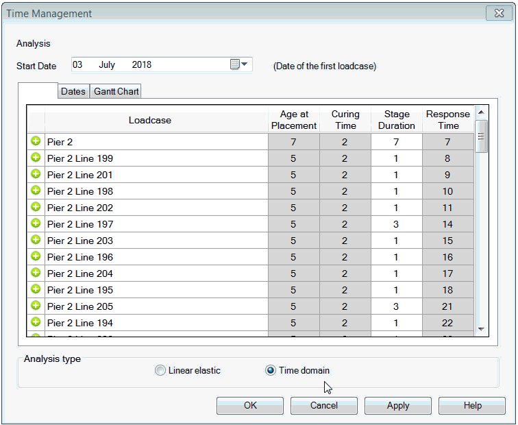
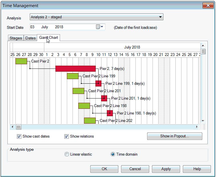
Time Management
Use the
time management facility to manage a simple construction schedule and easily adjust
the duration of pre-defined construction stages in a staged
construction analysis. Easily and
automatically update the total response time values in nonlinear and
transient controls that have been previously specified for each
loadcase of a staged construction analysis.
Staged construction with
LUSAS
-
Model full staged construction
with beams, shells and solid elements (some software only
permits beams to be used)
-
Full activation and
deactivation of elements is supported
-
Model any support condition
and add or remove supports as required during the
construction sequence
-
Sliding bearings may be modelled using nonlinear contact (slidelines)
-
Support and loading facilities
including temporary/traveller loads
-
Apply loads anywhere onto any
model
-
Change loading/stress/strain
over time and lock- in stresses, if applicable, between stages
-
Prescribed displacements or jacking loads may be used as spans
are completed
-
Time-dependent material
properties include stress related concrete creep and
shrinkage to CEB-FIP Model Code 1990, (and others) and includes creep
recovery
-
Custom time-dependent curves
for particular material properties and codes
-
Use single or multi-tendon
wizards to define and assign tendon properties and
time-stages to features of a model.
-
Steel relaxation, time effect
on elastic modulus, tendon post-tensioning losses from
creep, shrinkage, and superimposed loads
-
Cumulative effects can be
reported separately for each loadcase, such as
post-tensioning effects, or for the effects of just creep and
shrinkage
-
Incremental effects can also
be specified allowing you to view and assess the net changes
to the structure since the previous stage.
Animation of axial
forces in members during dismantling of the San Francisco-Oakland Bay Bridge East Main Span.
Use for
Use for
all types of staged construction methods and bridge types including:
-
Staged
placement of beams and slab for continuous structures
-
Cast
insitu span-by-span construction of continuous beams
-
Precast
segmental span-by-span erection
-
Cast
insitu balanced cantilever construction
-
Precast
segmental balanced cantilever construction
-
Progressive
erection of precast segmental decks
-
Incremental
launching
-
Balanced
placement for cable-stayed bridges
-
Composite
decks
-
Extradosed
bridges
-
Suspension
bridges
Span-by-span example
The erection of all segments
for a span in a set, which is then aligned, jointed, and
ultimately, usually, longitudinally post-tensioned together to
make a complete span. In LUSAS, this can be modelled
as a line beam model with optional fleshing of the deck
cross-section to show results contours.
The
animation below shows the construction sequence for the twin rib
span-by-span example shown (substructure not included).
The
analysis can incorporate post-tensioning
between stages, and creep effects as construction
continues, as required.
Balanced cantilever
The building of a bridge
superstructure from both sides of a pier in a scales-like
fashion.
Using LUSAS, creep
/ shrinkage analysis can incorporate an age attribute (for precast elements)
and checks on robustness
can also be made as, for example, where a segment may be
inadvertantly dropped by crane and where dynamic effects (impulse)
are important. 2nd order (P-delta) effects could also be included.
|
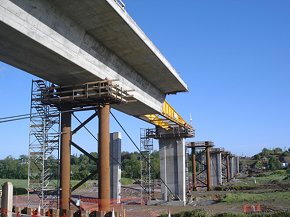
Incremental launching
Incremental launching
involves the casting of a continous
chain of bridge segments on-site adjacent to the actual
location of the bridge and then pushing the growing
superstructure out over temporary and permanent supports at
the bridge's location - as used in the construction of the Blackwater
Viaduct in the Republic of Ireland.
Using LUSAS, incremental
launching can be carried out for both in-line deck launching,
or for a curved deck launch. Modelling of incremental
launching can be done by activating and moving a
series of supports backwards under a model that is
incrementally being added to. This can be done via general
modelling facilities, or by scripting methods to automate the
modelling process.
|
|
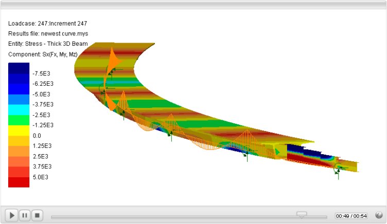
An example of this method for a
box girder bridge with a simplified nose is shown below.
Curved deck
launching
Click to play movie (in new window).
Staged
Construction Modelling : Case Study
The initial
proposed I95
Mississippi
River Bridge was designed to be a record-breaking, cable-stayed structure
linking the States of Illinois and Missouri in the USA, helping to
relieve traffic on existing bridges across the river. Designed
by Modjeski & Masters for its clients Missouri and Illinois
Departments of Transportation, staged construction facilities in
LUSAS Bridge were used to model an 800 day construction
period, followed by a 10000 day period to allow for creep
over that length of time.
Geotechnical / Soil-structure interaction modelling
Find out more
|