Additional Information
See the adjacent Software Information
links for general details regarding LUSAS Bridge software products.
Curved
Girder Analysis
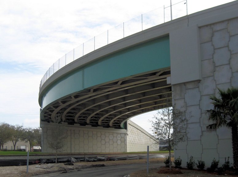
With curved girder structures significant torsional stresses must
be accounted for at the design stage and careful consideration is
also required to ensure their safe erection. To arrive at
meaningful results for curved girder bridges grillage-based
analyses are not sufficient. Full 3D modeling and analysis is
required to accurately model the beams and, in particular, to
derive the tension and compression forces in the �K� or �X�
frame bracing members. LUSAS Bridge is ideal for curved
girder analysis and has many useful modelling and results
processing features to help you optimise your design.
Composite deck modelling
Unlike some analysis systems LUSAS Bridge
allows you to idealise your composite deck/curved girder structure in a
number of ways:
The choice of which modelling
idealisation to use depends upon what is required from the results of
the analysis. For instance, if a curved girder analysis is being
performed and the lateral forces in the top and bottom flanges are
required then the shell element modelling and beam element modelling of
flange idealisations would be suitable but the beam element modelling of
the whole girder would not. Complete
3D modelling of a curved girder structure including cross frame bracing
allows the tension and compression in these members to be obtained. This
cannot be achieved using 2D grillage models.
| Shell
element modelling of the whole deck. |
Beam
element modelling of flanges. |
Beam
element modelling of the whole girder. |
|
|
|
|
| With
this modelling method discrete features are defined for the top
flange and slab because their materials are not identical. The
slab has an eccentricity to define a bending plane that is not
coincident with the top flange and these two components are
combined using an equivalence attribute. |
With
this, the shell elements representing the top and bottom flanges
of the girder are replaced by beam elements running along the
top and bottom of the girder with the appropriate properties for
the flange members. |
With
this, the girder is replaced with a single beam element having
appropriate geometric properties and an eccentricity to offset
the bending plane of the beam from the deck. |
| |
|
|
| Some common
questions...
Can LUSAS accommodate varying
widths and thicknesses of flanges?
YES -
Geometric dimensions and properties can be varied to exactly
match your proposed design.
Can slab and girder connections
be modelled as rigid connections; or with an interference mesh
between the slab and the girder; or can individual shear studs
even be modelled if thought necessary?
YES - Unlike
some analysis systems LUSAS Bridge allows you to idealise
your composite deck/curved girder structure in any way you wish.
Can LUSAS model areas of cracked
concrete - such as may occur in regions of slabs around and over
supports?
YES - The
cross-sectional properties of your structure can be varied along
the bridge deck.
Can LUSAS handle staged erection
analysis?
YES -
Elements in your model can be deactivated and re-activated to
mimic the erection process and show stresses and forces induced during the
construction process.
Can I load LUSAS models with
arbitrary truck loading?
YES - Vehicle
loading can be manually assessed or the Autoloader vehicle
optimisation facility will assess worst case loading patterns
for any point on your structure. LUSAS deals with this as
standard.
Can I isolate parts of my model
for more detailed results processing?
YES - The
useful group facility allows you to break down your model into
named components and this allows selective display of model
features or for isolated viewing of particular results.
Can I slice through my model to
get results at selected points?
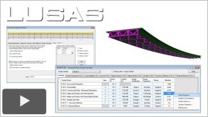
YES - A slice
section facility allows forces and moments to be obtained at any
chosen location on 3D beam and shell models and is of particular
use for curved girder analysis. It allows slice sections to be
defined at user-specified distances along the deck or along
individual girders. Slice sections are visualised, labelled on
the model, and results are written to a results window for
creation of force and moment diagrams if required.
Can I see the tension and
compression forces in the cross frame bracing members?
YES -
Diagrams of axial force in beam elements can be easily plotted
to assist you with the design of your bracing.
|
See case study: Analysis and design of Avenues Walk Flyover
Composite Deck Design
Carry out comprehensive
calculations for design members / multiple sections on steel or
steel/composite bridge decks using the appropriate Composite Deck
Design software option.
Design codes
currently supported:
See also:
|