Case Study
 Design Check of Post-tensioned Flyover Design Check of Post-tensioned Flyover
When CMPS&F were engaged to undertake the structural design of a
4-span curved flyover in Brisbane, Australia they decided to use LUSAS Bridge
analysis to check the design.
Dr Nick Stevens was CMPS&F's project manager for the structural
design. due to aesthetic requirements, he selected a continuous, post-tensioned, voided
slab type of construction. The bridge has a total length of 102m and consists of four
spans with a longest span of approximately 31m. The included angle of curve is 79 degrees.
The cross-section consists of a central trapezoidal section 6m wide and a deck
cantilevering 1.25-1.75m on either side. With an overall depth of just 1100mm the bridge
is particularly slender. For this reason it was decided to use finite element analysis to
undertake the design check.
To take full advantage of the benefits offered by finite element
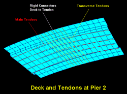
analysis, a fairly unusual modelling technique was used. All of the post-tensioning
tendons were modelled as separate elements. The reinforced concrete was modelled using
thick shell elements with the tendons being 3D bar elements, connected by vertical rigid
beam elements to the appropriate node in the plane of the thick shells. The profile of the
tendons in the model accurately representing the actual profile. The post-tensioning is
input by applying initial strains to all the elements representing the tendons. The
initial strain varies along each tendon in accordance with the friction losses.
This modelling approach offered several advantages over conventional
methods that do not separate out the tendons. Principally it allows the effects of
post-tensioning to be accurately modelled including all effects of creep, shrinkage,
relaxation, and secondary effects. Also, resulting moments and shears in the thick shell
elements are those that need to be resisted by the reinforced concrete alone. This
eliminates the need to remove the contribution carried by the tendon at a later date.
 The output from
the analysis included plots over the bridge deck of resultant forces and moments per unit
width (including in plane and out of plane shear). By using theory based upon the truss
analogy it was possible to combine the resultants for a particular load case so that
contour plots of reinforcing requirements could be produced. This in turn could be
enveloped over all relevant ultimate load cases to result in overall contours of
reinforcing requirements for the whole deck. In a similar manner contours of concrete
compression requirements could also be produced. The output from
the analysis included plots over the bridge deck of resultant forces and moments per unit
width (including in plane and out of plane shear). By using theory based upon the truss
analogy it was possible to combine the resultants for a particular load case so that
contour plots of reinforcing requirements could be produced. This in turn could be
enveloped over all relevant ultimate load cases to result in overall contours of
reinforcing requirements for the whole deck. In a similar manner contours of concrete
compression requirements could also be produced.
To enable the bridge to be constructed with minimum traffic disruption
it was necessary for it to be built in two stages. It was important to model this to
determine its effect on the overall bridge response. This was easily accommodated in
LUSAS. In modelling the first stage the model of the entire bridge was used but with the
unconstructed part having its elements 'de-activated'. A unique feature of LUSAS allows
the combination of results from different analyses with varying geometrical, support and
material properties provided that the mesh is identical or forms a subset of the full
model. Using this feature the results for this first stage could then be combined with the
results from other runs with loading on the full bridge to accurately model the effect of
construction staging.
The results of the analysis generally indicated significantly lower
reinforcing requirements than resulted from the conventional analysis. The potential
saving of this was largely reduced by satisfying code requirements for minimum
reinforcing. However , according to Dr Stevens: "The real benefit of using finite
element analysis is a high level of confidence in the results and in the actual service
and limit state performance of the bridge itself".
Find out more
|