Bridge analysis, design + assessment

Case Study

Assessment of Brick Vaulted Arches at Glasgow Central Station

  • Linear elastic modelling of a multi-span vaulted arch structure for load assessment
  • Nonlinear analysis of a single vaulted arch using a multi-crack concrete material model
  • Adequacy for RA8 loading confirmed

At Glasgow Central Station, Network Rail wanted to increase the station's capacity by replacing a short stay car park at platform level with two additional tracks and platforms. The Platforms 12 & 13 Design & Build Contract required support to be provided to two, 340m lengths of new permanent way, 90m of which was supported by brick vaulted arch geometries constructed in the early 1900’s and not previously exposed to rail loading. URS worked as the designer for Balfour Beatty and used LUSAS Bridge analysis software to assist with its assessment of the vaulted arch structures and confirmed their adequacy for the required RA8 assessment loading.

Overview

Glasgow Central Station was constructed at the beginning of the 20th century and has Category A listed status. It is the Northern Terminus of the West Coast Main Line and handles 34 million passengers a year, making it one of the busiest stations in the UK outside London. All tracks at the station are between 7 and 8 metres above existing ground level so support for the new tracks needed to be provided by existing steel structures, existing masonry vaulted arches and some new build work. Geotechnically the site is complicated. Due to proximity of the River Clyde, a varied mix of alluvial clays, sands and silts are present, in varying depths and layering, and with significant differences over the length of the site in the direction of the river. The theoretical soil strength was low, suggesting that the allowable bearing pressures were being exceeded by the existing permanent load, but there was very little observable cracking or other signs of distress in the arch structures to support this. The arches appeared to be in generally good condition considering the masonry had been constructed 100 years ago. It was concluded that the slow construction method had allowed settlements to occur during construction that had been continually corrected as the works progressed leaving minimal post-construction settlement or cracking.

Before: Short stay car park between platforms After: New permanent way installed

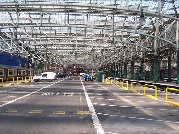
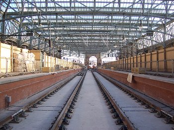
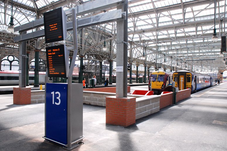
Installation of the two new tracks required the removal of the short stay car park slab and support walls, and replacement with the slab-track and permanent way. This would result in a slight reduction in the permanent loads on the substructure but live loads would increase from light road vehicle use to RA8 assessment loading for goods trains. As a result the total load would increase by up to 20%. New permanent works proposed as part of the platform design and build contract would enhance the foundation bearing capacities by bridging the gap between the existing piers. In addition, a bridging slab would prop the existing pier foundations and also help to prevent slip planes forming between the sets of foundations by providing a single, long foundation instead.

Modelling with LUSAS

The assessment method adopted was a progressive one. It started with the creation in LUSAS of a 3D linear elastic global solid model of an arrangement of substructures to get a feel for the stresses involved and also to assess the bearing pressures under the foundations and provide input with regard to spring stiffnesses for use in a later nonlinear analysis. The region of substructure chosen for modelling (shown below) was considered to have the least restraint. The void seen in the centre of the model was to be filled with new reinforced concrete works but these would not be supporting the existing structures.

Geometry model for an initial linear elastic assessment of a selected region of substructure

Nonlinear analysis

A solid nonlinear model of an individual vaulted arch was created for detailed analysis using the LUSAS multi-crack concrete material model. Initially, brick properties were obtained from CIRIA C656. Dr Danny Boothman, project engineer at URS said, "Although we were looking at a brick arch it was felt that because of the number of bricks in the arches it was approximating to a homogeneous material and essentially the mechanism for load transfer was very similar to low strength concrete with minimal tensile strength and thrust generating through the arches". Haunching and back-fill was modelled using a Mohr-Coulomb material model with a low tensile strength and a high angle of friction. Boundary conditions were modelled as sprung, free and fixed, although the material models employed prevented a significant build up of tension.

Geometry model for a nonlinear analysis of a single vaulted arch Calculated crack patterns under existing permanent loading

A significant amount of time was spent on parametric sensitivity studies to identify critical input parameters and provide upper and lower bound values for the LUSAS concrete material model. Danny Boothman explains, "Many parameters needed to be defined for the multi-crack concrete model and we found that some were more sensitive than others - particularly the uniaxial tensile strength and the fracture energy per unit area. The input parameters for the LUSAS models were calibrated against the observed effects of the dead loads on the arches. Additional loading to represent the RA8 rail loading was then applied and the resulting cracking and deflections were used to demonstrate the adequacy of the structures for RA8 loading. As anticipated, the results were particularly sensitive to the support stiffnesses at springing level, as well as some material parameters including tensile strength - both of which are difficult to predict reliable values for."

Stresses from RA8 loading Stresses from RA8 loading (underside of arch)

Summary

Overall this was a challenging assessment, completed using the multi-crack concrete model in LUSAS, and calibrated against existing conditions. Because a relatively novel analysis was used to undertake the assessment using the pre-construction condition as a calibration basis for the modelling it would have been beneficial to have had load test data for higher loadings to corroborate the results, but this was not possible. However, a number of areas of conservatism in the analyses carried out were felt to be sufficient to justify the approach taken:

  • The backing layers to the arch were actually found to be mass concrete and therefore vertically self supporting. 

  • The calibration of the FE model against observations indicated that the model was conservative, predicting greater cracking under existing loads than was seen on site. This conservatism was acceptable since the purpose of the analysis was to demonstrate adequacy under RA8 loading rather than determine a maximum load capacity.

  • The load spreading benefit of the reinforced concrete slab track was ignored.

  • A third party check using discrete element modelling corroborated the results and reached similar conclusions.

  • Platform use is limited to very low speed passenger trains (significantly below RA8) because Glasgow Central is a terminus station.

  • Monitoring of the vaulted arches under rail loading was also undertaken to further validate the findings of the assessment.

Danny Boothman sums the project up as follows, "Although there was new-build work on this project which might have grabbed the headlines from a photographer's point of view, the real crux of this project from a design/assessment perspective was being able to justify the new railway tracks over 90m of old vaulted arches."

"Although there was new-build design work on this project, which might have grabbed the headlines from a photographer's point of view, the real crux of this project from a design/assessment perspective was being able to justify the new railway tracks over 90m of old vaulted arches."

Dr. Danny Boothman, Project Engineer, URS.


Find out more

LUSAS Bridge

Software products

Software selection


Other LUSAS Bridge case studies:


Software Information

  Bridge / Bridge plus
green_arrow.gif (94 bytes) Software overview
green_arrow.gif (94 bytes) Modelling in general
green_arrow.gif (94 bytes) Advanced elements, materials and solvers
green_arrow.gif (94 bytes) Load types and combinations
green_arrow.gif (94 bytes) Staged construction modelling
green_arrow.gif (94 bytes) Geotechnical / Soil-structure modelling
green_arrow.gif (94 bytes) Analysis and design
green_arrow.gif (94 bytes) Design code facilities
green_arrow.gif (94 bytes) Viewing results
green_arrow.gif (94 bytes) Software customisation

  Bridge LT
green_arrow.gif (94 bytes) Software overview

  Choosing software
green_arrow.gif (94 bytes) Software products
green_arrow.gif (94 bytes) LUSAS Bridge LT
green_arrow.gif (94 bytes) LUSAS Bridge
green_arrow.gif (94 bytes) LUSAS Bridge Plus
green_arrow.gif (94 bytes) Software selection
green_arrow.gif (94 bytes) Software options

green_arrow.gif (94 bytes) Videos
 
green_arrow.gif (94 bytes) Case studies

  Application areas
green_arrow.gif (94 bytes) Footbridge design
green_arrow.gif (94 bytes) Movable structures
green_arrow.gif (94 bytes) Rail solutions
green_arrow.gif (94 bytes) Arch bridges
green_arrow.gif (94 bytes) Major crossings
green_arrow.gif (94 bytes) Soil-Structure Interaction Modelling

  Additional information
green_arrow.gif (94 bytes) Linear and nonlinear buckling analysis
green_arrow.gif (94 bytes) Curved girder analysis
green_arrow.gif (94 bytes) Integral or jointless bridges
green_arrow.gif (94 bytes) Post-tensioning
green_arrow.gif (94 bytes) Concrete modelling
green_arrow.gif (94 bytes) Interactive Modal Dynamics
green_arrow.gif (94 bytes) LUSAS Programmable Interface (LPI)

  General information
green_arrow.gif (94 bytes) Hardware specification
green_arrow.gif (94 bytes) Licencing and Networking options
green_arrow.gif (94 bytes) Software prices
green_arrow.gif (94 bytes) Documentation
green_arrow.gif (94 bytes) Links page
 

Request information


innovative | flexible | trusted

LUSAS is a trademark and trading name of Finite Element Analysis Ltd. Copyright 1982 - 2022. Last modified: March 07, 2023 . Privacy policy. 
Any modelling, design and analysis capabilities described are dependent upon the LUSAS software product, version and option in use.