Case Study
The assessment of box girder diaphragms with weak welds
- box girder crossheads on viaduct structures
- nonlinear yield check analysis
- strengthening work proved unnecessary by LUSAS
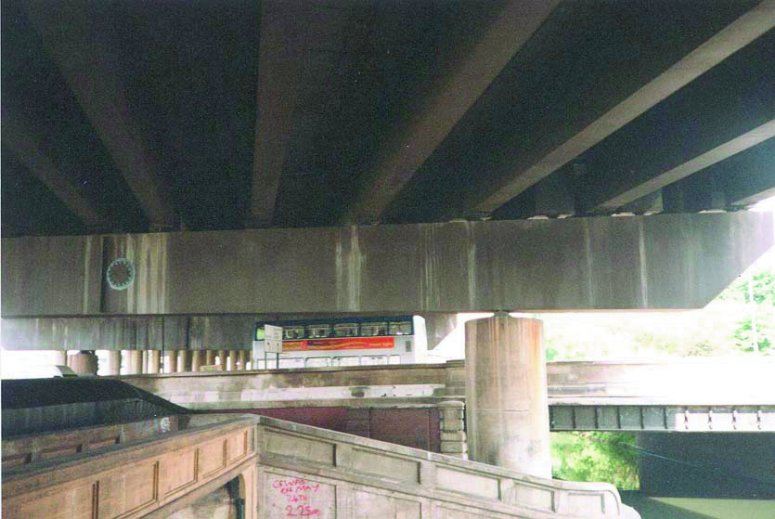
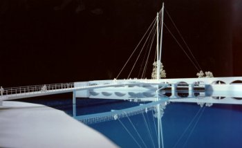
The Midland Links Viaducts carry the M5 and M6 Motorways around
Birmingham. A number of spans are supported on steel box girder crossheads and contain
strengthening details, added in the period following publication of the Merrison Report, which are not easily amenable to assessment using
codified methods. Maunsell Ltd
have
undertaken detailed nonlinear analysis using LUSAS Bridge, and have proved the
integrity of the diaphragms at the ultimate limit state.
Initial hand calculations to the methods in BS 5400 Part 3 indicated
that panels within the support diaphragms of these box girders would yield below ultimate
limit state loading. In addition, simple analysis suggested that the intermittent welds
between the diaphragm and the vertical stiffeners were also liable to yield. A linear
elastic analysis using LUSAS Bridge confirmed this, and a detailed materially and
geometrically nonlinear analysis was undertaken to prove the integrity of the diaphragms
at the ultimate limit state.
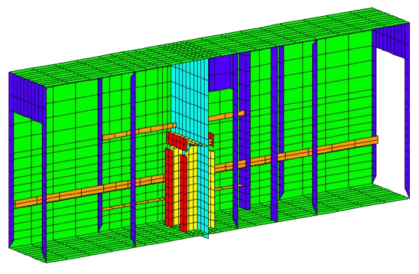
The diaphragm and the adjacent steel
plates of the structure were modelled using four noded thick shell elements. The diaphragm
stiffener welds were modelled using elastic / perfectly plastic joint elements with six
degrees of freedom. Elastic, plastic, and tension-hardening properties were assigned to the
shell elements. Yield forces for the joint elements were specified so that the resultant
forces in the joints were limited to values corresponding to the weld yield stress
predicted by assessment code BD21/97. The stiffnesses of the joints were chosen so that
onset of yield in the joint elements corresponded to a resultant weld deformation of no
more than 0.10mm, a value supported by research evidence.
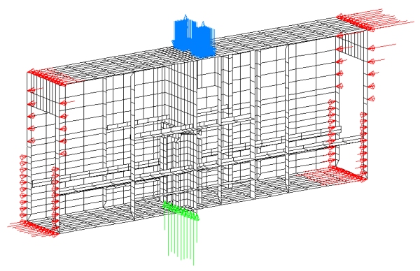
| Moments, shears and torsions at the ends of the
shell model and the reaction at the diaphragm base for the critical loadcase were
determined using a line beam analysis. These loads were applied to the model as
concentrated nodal loads. The load datasets were specified using variations, to simplify
input of the linear stress distribution produced by bending in the plane of the webs. To
allow for geometric imperfections within the diaphragm plates, a suitable deformed mesh
shape was created by analysing a through thickness temperature variation within the
diaphragm as an elastic loadcase. The resulting deformed mesh was then tabulated with the
structural loads.
|
  |
|
|
| The extent of yield within the structure
was identified at each load increment by plotting yield flags. Animations of the deformed
mesh shape and stress contour plots at successive load increments showed how the diaphragm
redistributed load as it approached its limiting strength. Out of plane nodal displacement
histories for nodes within the diaphragm were plotted against total load factor to confirm
that buckling was not appreciable. The movement of the joint elements were output at each
load increment and a spreadsheet was used to plot graphs of the displacement profile along
the weld line for every load increment. These graphs proved that the deformation of the
welds would not exceed the limiting value of 1.0mm set as a safe limit, and showed that
potentially difficult strengthening work was unnecessary.
|
|
The Merrison Report was
the product of a Royal Commission set up following a number of high profile, catastrophic
collapses of box girders during the late 1960’s, including the Westgate Bridge in
Australia and Milford Haven in South Wales. The report included detailed design and
workmanship rules for box-girder bridges which were used to check all existing box
girders, and then used for detailed design until the introduction of BS5400: Part 3 in
1978. The Part 3 rules for diaphragms, in particular, are simpler to implement in a
"blank sheet of paper" design situation than the Merrison interim rules.
Find out more
Other LUSAS Bridge case studies:
|
|
Software Information
|