Case Study Case Study
Share this
article
Demolition of Paseo Bridge
-
Demolition
analysis of a self-anchored suspension bridge
-
Staged
construction modelling of existing structure including all
renovations made
-
Staged
demolition analysis using global and local models to ensure safe
dismantling
Genesis
Structures was appointed
by the Paseo Corridor Constructors joint venture to carry out a
detailed demolition analysis of the Paseo Bridge in Kansas City,
Missouri. Using LUSAS Bridge analysis software, Genesis Structures
built a model of the existing structure incorporating all major
renovations made to it during its lifetime. This was further developed
to include all proposed demolition/removal steps. An additional model
was developed to assess the lowering of the main suspension cables and
another model investigated detailed stresses and effects upon the
pylon base and anchor bolt system. All analyses proved that the
intended demolition sequence could be undertaken safely.
Overview
Paseo Bridge was designed by Howard,
Needles, Tammen and Bergendoff in the early 1950's, and built by
American Bridge Co. in 1954. It was a four-lane, self-anchored
suspension bridge that carried I-29/35 and State Route 71 over the
Missouri River in Kansas City, Missouri. Suspended spans of 308, 616
and 308 feet, south approach plate girder spans of 90 and 174 feet and
north approach plate girder spans of 219 and 110 feet carried two
13-ft traffic lanes in both directions separated by a 4-ft median.
When first opened to traffic it was the longest self-anchored
suspension bridge constructed in the world.
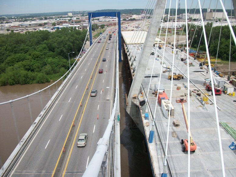
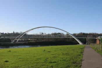
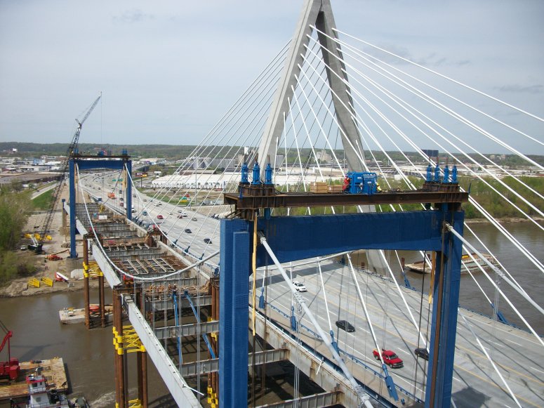
As part of the kcICON project, funded
by the Missouri Department of Transportation (MoDOT), a new iconic
river bridge - the Christopher S. Bond Bridge - was constructed
adjacent to, and to
replace, the existing Paseo Bridge. Design and construction for the new bridge
was carried out by Paseo Corridor Constructors (PCC), a joint venture
partnership of Clarkson Construction Company, Massman Construction Co.
and Kiewit Construction. PCC retained Genesis Structures to perform a
demolition analysis of the existing bridge.
Bridge Construction
The 136-ft tall towers were of plated
steel construction and were braced with upper and lower struts.
Suspension cables passed through holes in the upper struts and sat on
cable saddles that were supported on a set of 12, 6" diameter by
30" long rollers that rested on a substantial steel plated
support. Pairs of hangers suspended along each cable supported the
deck superstructure. For the deck itself, a 7" non-composite
concrete roadway slab sat on 21" deep stringer beams that spanned
between 6-ft deep transverse floor beams which, in turn, spanned
between the massive 10-ft deep longitudinal plated stiffening girders.
Hinged connections in these girders at mid-span and at each tower
position used 13" diameter steel pins to accommodate rotational
movement and thrust during construction. Following the placement of
the concrete deck, temporary bolted connections previously made at
these hinge positions were removed and cover plates were riveted to
complete the connection and make the stiffening girder continuous.
During construction the movement of the saddles was restrained by the
use of locking angles which were removed at particular stages to
allow the saddles to move longitudinally and allow re-positioning of
the top of the towers. After the construction of the concrete deck and
on completion of construction, the tops of the towers were adjusted for
the final time and permanent locking angles were fitted to restrict
any further movement.
Construction modelling
Prior to carrying out a demolition
analysis a detailed staged construction model of the existing bridge
needed to be created. Original construction documents provided a
suggested erection sequence and based upon this a preliminary
evaluation of the required demolition was performed. During this
evaluation, PCC was able to obtain the original erection plans that
were developed by American Bridge Co. This provided a great deal of
additional information to assist with the modelling
process and included the actual constructed geometry of the stiffening
girders and the main suspension cables as well as the exact
fabrication lengths used for the suspension hangers.
From all the construction information
available, Genesis Structures was able to develop a very detailed and
accurate model which not only represented the actual construction
sequence but also incorporated all renovations made to the structure
during its lifetime. This included an additional wearing surface and the
replacement of the main stiffening girder bearings which resulted in an
approximately 3" lowering of the deck system. As a result of this
modelling process the displacements and stresses seen during the bridge's
construction could be appreciated and the forces in the main cables
and hangers could be obtained for its final in-service condition. A
survey of the existing structure confirmed the accuracy of the LUSAS
modelling process. Major milestones
in the as-built analysis model included:
- Lifting and lowering the primary stiffening girder
during construction
- Connection of the suspension hangers
at the
appropriate time step
- Modelling and locking/unlocking the main cable roller
saddle
- Lowering of the superstructure to accurately account for a bearing
replacement
- Modelling the addition of a
wearing surface overlay.
|
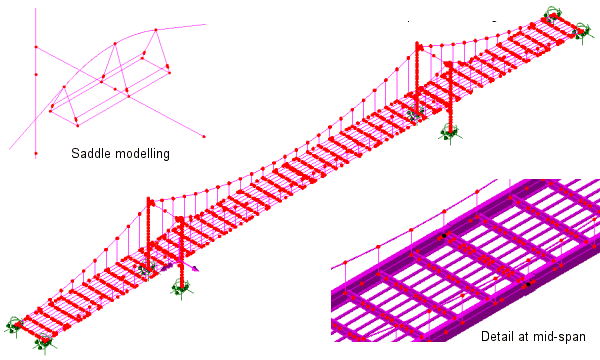
|
|
Construction
modelling |
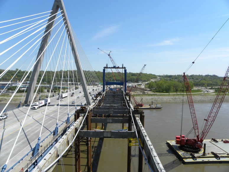
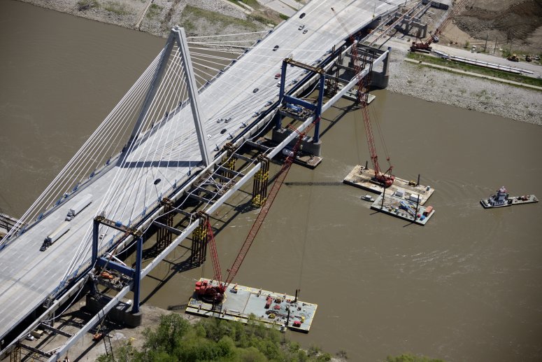
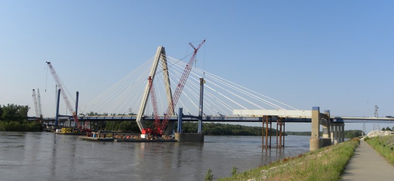
Demolition modelling
After developing a comprehensive
demolition sequence with PCC, Genesis Structures then appended all of
the proposed demolition/removal steps to the erection model to assess all the effects on the structure. The
wearing surface, slabs, stringers and selected floor beams were removed from the
superstructure to leave a minimum structural configuration. To assist
with the demolition four falsework
towers, each comprising 36" diameter pipes braced in a six-pile
configuration, were installed under the centre span. Jacks on these
towers and a strand jack system supported on the existing bridge piers
raised the longitudinal girders and removed the remaining
superstructure load from the main suspension cables. Major
milestones in the demolition analysis model included:
- Evaluating the effects of unlocking
the main cable roller saddle
- Monitoring of the locked-in forces in the
main towers
- Sequential removal of the existing
superstructure
- Lifting analysis of the
superstructure to remove the load from the main suspension cable
- Detailed analysis of both the
lowering of the main suspension cables and the existing
bridge pier anchor bolt system
|
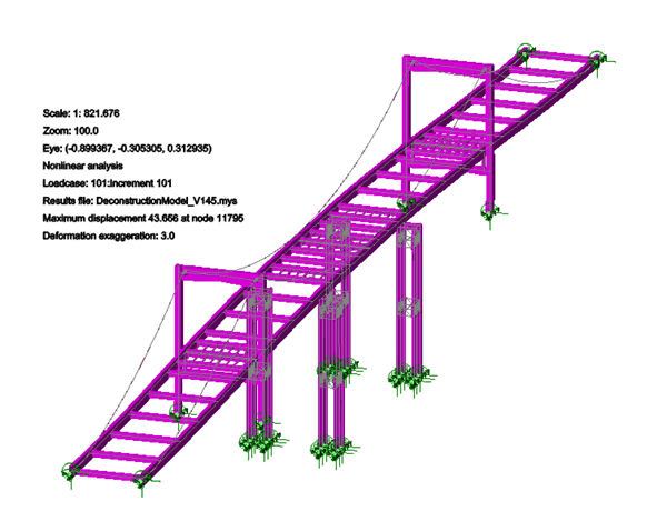
|
|
The latter
stages of the demolition
modelling of Paseo Bridge |
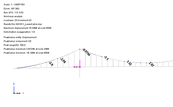
Cable lowering
Following the removal of the
superstructure load from
the cables, a separate LUSAS model was developed to
evaluate the lowering of the main cable to the deck level for removal.
This was done by using strand jacks fixed to the upper struts of
the towers to lower the upper strut and saddle in stages by amounts
specified by Genesis Structures as a result of the LUSAS analysis.
Additional loadcases were defined for the cable lowering model with
pin or roller supports being inserted as
necessary at the positions where the cable touched down on the frame,
falsework, girder or floor beam supports. By this process the lowering of the
cables was modelled and the displacements in the main cables and
reactions at each stage could be seen.
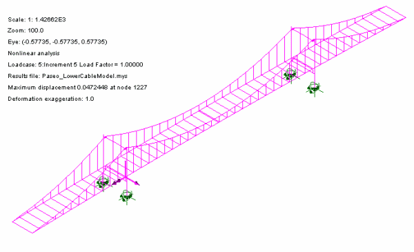 |
|
Cable lowering
model for Paseo Bridge |
 |
|
Animation of
cable lowering for Paseo Bridge |
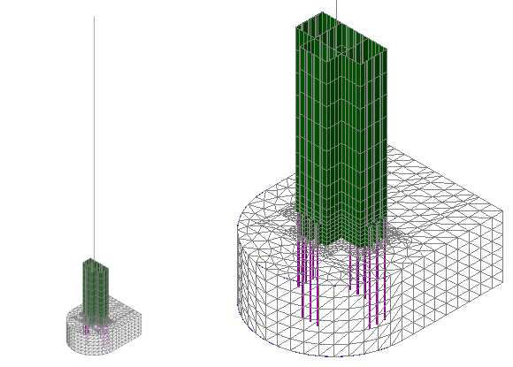
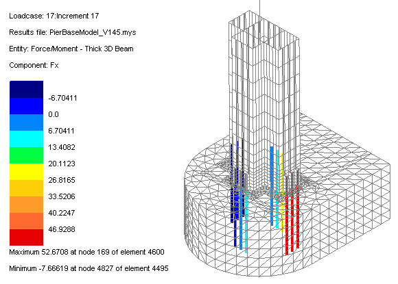
Tower base modelling
To investigate the effects on the tower
base system from dead and wind loading effects, superstructure
lifting, cable lowering operations and for situations when
the saddles were either released or locked during particular
demolition stages yet another model was used. For this, the varying
geometric properties of a pylon were modelled with shell elements for
the lowest 24-ft with the remainder of its height being represented by
thick nonlinear beams. Solid elements modelled the 5" thick steel
pylon base plate and friction slidelines were used on their contacting
surfaces to represent the interaction of the base plate with the concrete
pier. Beam elements modelled the 10-ft long, 2.5" diameter anchor
bolts cast into the concrete piers. Concrete bearing stress,
base plate bending stress and maximum tensile forces in the anchor
bolts were obtained for a set of considered loadcases.
|
|
|
Tower base
modelling |
|
|
|
Illustrative
tower base results plots for a selected loadcase |
In
summary
Using LUSAS, Genesis
Structures was able to accurately model construction techniques used
in 1954 to determine the state of stress and geometry of this major
self-anchored suspension bridge as the contractor prepared for the
demolition. Knowing the exact state of stress in the structure allowed
for a complete understanding of the demolition process during all
stages including critical unbalanced lifting and lowering operations.
David Byers, President of Genesis Structures said: �Being able to
construct and deconstruct a major nonlinear structure like the Paseo
Bridge in a single analysis model was critical in the success of the
demolition.�
"Being able to
construct and deconstruct a major nonlinear structure like the Paseo
Bridge in a single analysis model was critical in the success of the
demolition."
Dr
David Byers,
President, Genesis Structures
Share this
article
Find out more
Other LUSAS Bridge case studies:
|