Case Study
Static and
Dynamic Analysis of the Construction Phases of Storebaelt East Suspension Bridge
- 2.7km long suspension bridge
- static and dynamically nonlinear analysis
- modelling of bridge construction process
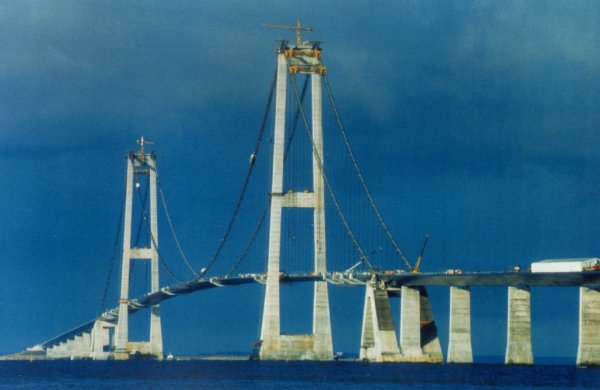
The 6.8km long Storebaelt East Bridge spans between the Sprogo and
Zealand islands in Denmark and includes a 2.7km long major suspension bridge with a 1624m
main span and 2 side spans of 550m. DE MIRANDA Associati
(DMA) , based in Milan, Italy, used LUSAS Bridge analysis software to provide
advice and structural analysis on the construction of the bridge to their client
Gec-Alsthom Sdem, who were the erectors. Many static and dynamic geometrically nonlinear
LUSAS analyses were undertaken by DMA during the engineering construction process.
| Nonlinear static analysis
Static step-by-step analysis was used to analyse all
construction stages in order to obtain the following:-
- Incremental and absolute displacements in order to control the bridge
geometry during the construction process.
- Forces in the final and temporary hangers for checking purposes.
- The temporary and final length of hangers to allow the matching of
segments during installation and to get the design prestressing moments in the deck at the
end of the construction.
- Forces in temporary connections in the different construction stages
under the action of construction loads and wind buffeting.
|
|
|
Global analysis of the bridge during construction was essentially an
incremental analysis but with many special features:-
- Progressive activation of hanger and deck elements and corresponding
loads in a highly nonlinear context.
- Prestressing of some hangers and changing of their temporary length by
shimming and de-shimming their base plates in order to match the deck segments.
- Prestressing.
- Progressive changing of internal restraint conditions caused by the link
between two adjacent segments changing during the construction process from no link just
after lifting, to a hinged link after the release of the hoisting ropes, to a rigid
contact link when the bottom gap closes but the joint between segments has not yet been
welded, and then finally to a rigid link after the joint is welded.
|
The analysis required many separate nonlinear analyses and used
interface programs to automatically manage the incremental and partial results. This gave
for each step both the final (actual) situation, in terms of displacements and forces, as
well as the incremental one. This analysis was performed before the current "staged
construction" capability was introduced into LUSAS so the benefits of this particular
facility could not be used. After some tuning of analysis parameters, the accuracy of the
results from LUSAS for nonlinear problems of this sort was confirmed by measurements on
site. As a result, the deck was erected without geometrical problems and with good
matching of segments. In fact, the difference between the theoretical and actual gap
between two segments during the last critical phases, and after installation of more than
2600m of deck and more than 100 chained nonlinear analyses was less than 10 mm.
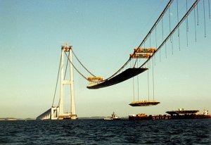
Nonlinear dynamic analysis
The aim of the dynamic analysis was to
analyse the critical phases in lifting the 550t deck segments from a barge taking into
account the wave motion, the lifting speed and the highly nonlinear behaviour of the
structure caused by having the main cables in place, a part of deck installed, hoisting
ropes and a suspended deck segment. The main objectives were to compute the dynamic
amplification factor during the first steps of lifting in the worst wave condition (when a
design wave drops down the barge at the start of lifting) and to check the possibility of
dangerous re-contact between deck segments and the barge during the first few seconds.
|
|
The
dynamic analysis was performed in two steps: the first one was undertaken to compute
frequencies and modes of vibration in the critical phases; this allowed tuning and
adjusting of the analysis features, such as the integration time and the time steps for
the successive calculations; and in the second step a nonlinear time history analysis was
carried out to obtain the required dynamic amplification factor along with the absolute
and relative displacements of the deck segment during the lifting process.
Find out more
Other LUSAS Bridge case studies:
|
|
Software Information
|