Case Study
Share this
article
Seismic
Resistant Viaduct Design for the Taiwan High Speed Rail Project
-
Pile-soil interaction modelling
for High Speed Rail viaduct structures
-
Automated viaduct model building
-
Multi-modal spectral response
analysis
Faber Maunsell,
a leading consulting firm for seismic design work, used LUSAS Bridge
to assist in the design of seismic resistant viaduct structures
and station guideways for Contract C270 on the Taiwan High Speed
Rail Project. Response spectrum analysis with LUSAS determined
forces in columns. Track-structure interaction analysis derived
relative movements and stresses within the rails under earthquake
loading. Nonlinear soil-structure analysis determined stresses in
piles and pilecaps. Solid element modelling of the end-blocks for
the proposed post-tensioning system and shell element modelling of
the precast superstructures helped produce local bending moments.
The end result? An economical design within a demanding project
time-scale.
|
Overview
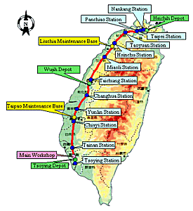
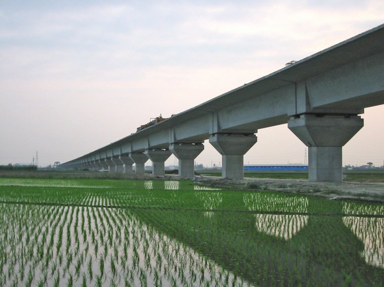
The 345km long High Speed Rail
route runs from Taipei City in the North of the country to
Kaohsiung City in the South. It will allow trains to travel at a
top speed of 300 km per hour. Split into numerous design
contracts, Contract C270 requires the design of 38km of standard
viaducts through Changhua, Yunlin & Chiayi Counties and a
station guideway at Yunlin.
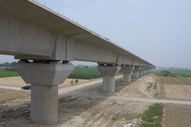
On Contract C270, the viaduct is up
to 28m high, and made up of 35m long precast post-tensioned
concrete box girders simply supported on single columns. The deck
units have free sliding mechanical pot bearings at each corner.
Shear keys at either end of the span provide transverse restraint
with one end fixed longitudinally. Bored piled foundations of 2m
diameter and up to 60m long support the viaduct. Station guideways
are of similar construction but with twin box-girders and RC
portal-frame supports.
|
|
Analysis
Requirements
The viaduct needed to meet three
key requirements: strict ride performance criteria set by the
client for normal operating conditions; remain within the elastic
range and restrict movements to specified values during a
significant seismic event so that a train may stop safely; and to
support the design loads and suffer only repairable damage from
the maximum design earthquake. To achieve these requirements four
distinct analyses involving the use of local and global LUSAS
models were required in order to prove the suitability of the
design.
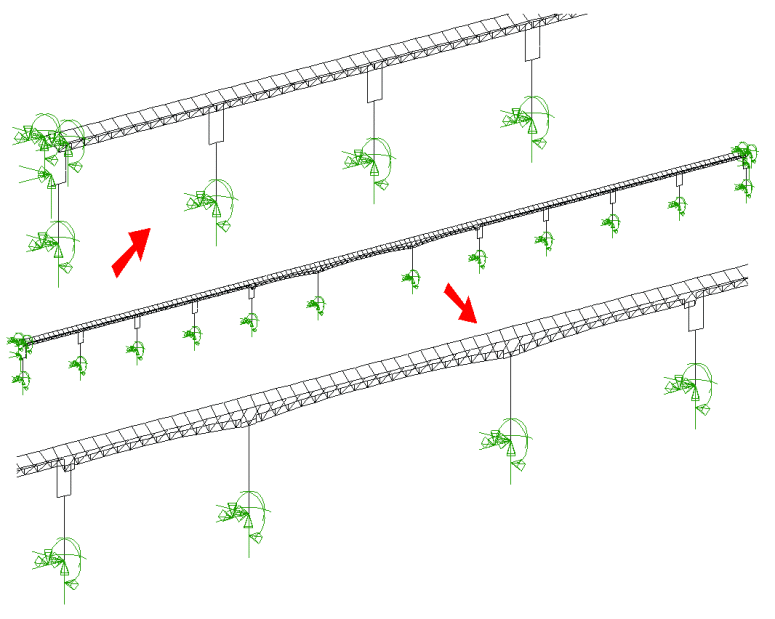
To analyse the entire 38km long
viaduct required the creation of 70 separate models. Faber
Maunsell
introduced automation wherever possible to enable the analysis to
be carried out efficiently. A Visual Basic Script was written to
read geometric data for the viaduct, such as column dimensions,
span lengths etc from an Excel database and built 3D beam models
in LUSAS for the global seismic analysis and track-structure
interaction automatically. This reduced the cost of creating new
models and provided confidence that the models were "machine
perfect" every time. In these models, joint elements were
used to represent concentrated masses, foundation stiffnesses,
bearings and shear-keys.
Global Seismic
Analysis
For each model, acceleration
response-spectrum analyses were carried out and the effects of up
to 200 modes were combined using the CQC method. Analyses were run
in three orthogonal directions separately and combined according
to the project requirements. In these analyses the stiffnesses of
the adjacent piers could vary significantly, particularly in the
station guideways and at non-standard spans. The multi-modal
spectral response analysis determined the seismic demand allowing
for variation in pier stiffness, which would not have been
possible using single-mode equivalent static calculations. From
these global analyses column design forces were obtained and used
for reinforcement design.
|
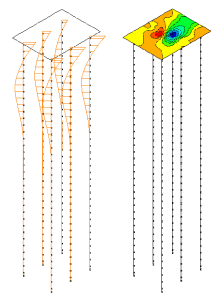
Foundation
Analysis
For the pile and pile cap analyses
3D beam and shell elements were used with Winkler springs
representing the nonlinear soil-pile interaction. Patch loads
representing forces due to plastic hinges forming in the columns
were applied to the shell elements that modelled the pilecap.
The design ground acceleration in
this contract could exceed 0.6g due to near-fault zones and the
LUSAS analysis permitted stresses in the piles and pilecaps to be
determined allowing for nonlinear soil behaviour. The models were
also used to calculate the translational and rotational
stiffnesses of the foundation which has a significant effect on
the earthquake loads predicted by the response spectrum analysis.
The foundation models were used to
obtain pile design forces and moments, and then by slicing
sections through critical sections of the pilecap, Clarke-Nielsen
forces were derived for reinforcement design.
|
|
Track-Structure
Interaction Analysis (TSI)
For each automatically created
model, design response spectrum-equivalent earthquake records were
applied to column bases in three directions simultaneously. This
was done by using prescribed accelerations controlled with
loadcurves. The columns were made as slender and flexible as
possible to lengthen the structure periods and hence reduce the
seismic demand on them. However, running contrary to this, it had
also to be demonstrated that the substructure was sufficiently
stiff to ensure safe operation of the railway during Taiwan's
frequent earthquakes and to allow the safe stopping of a train
during a seismic event should the need arise. The TSI analysis
predicted less conservative relative movements between adjacent
superstructures than a hand analysis, because it could allow for
the restraint provided by the continuous welded rails. The LUSAS
analysis also allowed direct calculation of stresses in the rails
under earthquake loading. From the TSI analysis relative
displacement histories for adjacent girders and stress histories
for rails were obtained. By enveloping the results of all time
steps maximum design values were obtained.
Superstructure
Analysis
For the superstructure analysis
solid modelling was required to determine stresses due to
distortion of end diaphragms and equilibrium effects within
anchorage zones in the precast box girders. To do this, patch
loads representing the prestress, bearing loads and seismic buffer
force were applied to the model. Stresses produced were integrated
to give forces and moments at each section in the end-blocks and
results were used for reinforcement design.
"The versatility of LUSAS
Bridge coupled with the technical expertise within our Group
helped produce an economical design for the extreme seismic
performance criteria of the Taiwan project with its demanding
programme and construction constraints."
Kandiah Kuhendran,
Project Design Manager, Faber Maunsell
Share this
article
Find out more
Other LUSAS Bridge case
studies:
|