Case Study
Dynamic Analysis of the Hungerford
Footbridges
- cable stay footbridges
- dynamic analysis
- assessment for deliberate vandalism
Westminster
City Council organised an international design competition in 1996 on behalf of the
Cross River Partnership, a group formed by public and private bodies whose aim is to
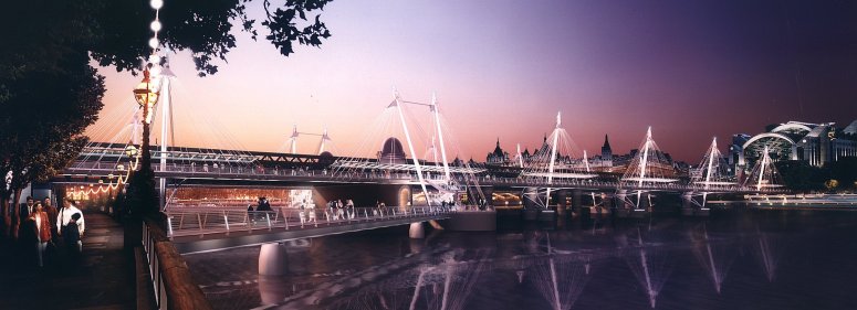
promote links across the Thames. The winning team comprised engineers WSP Group and architects Lifschutz Davidson. The scheme consists of two
new footbridges, one on each side of Charing Cross railway bridge, and two link bridges
which connect the South Bank to the Surrey pier of the railway bridge. LUSAS Bridge
was used to calculate the dynamic response of the bridges and to generate the parameters
for wind tunnel tests.
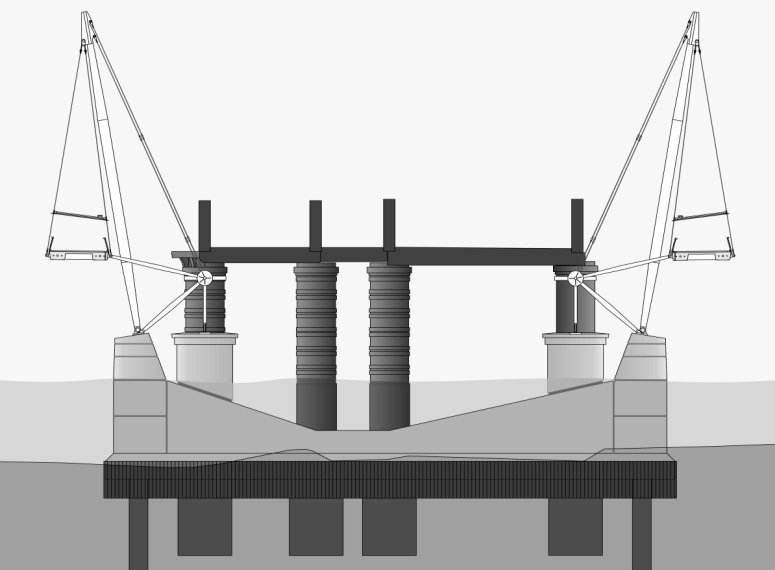
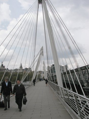
The two multi-span main footbridges are
320m long and 4.7m wide. They comprise pre-stressed concrete edge beams connected by a
structural slab and downstand ribs. The decks are suspended using arrays of cable stay
rods from inclined steel pylons. Steel cable backstays hold the 25m high pylons at the
correct inclination, and piled foundations provide vertical support.
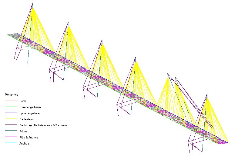
Using LUSAS, an eigenvalue analysis was initially undertaken and a
series of closely spaced mode shapes were extracted; the fundamental mode was found to be
at 0.82 Hz. This was considered low enough to cause concern and therefore a series of
transient (step-by-step) dynamic analyses were performed. The main bridges were firstly
checked against the limiting value of acceleration, due to a 180N sinusoidal dynamic load,
specified in the UK's Department of Transport Standard BD 37/88. Secondly in order to
assess the effects of deliberate vandalism, the acceleration due to a group of people
jumping up and down at the lowest natural frequency of the deck was also assessed. The
same limiting acceleration value permitted by the sinusoidal dynamic load assessment was
used and measured adjacent to the nearest jumping person. It was assumed that, if a group
of people cannot cause appreciably large accelerations that can be felt by others, then
nobody else will join in. In both instances the results were found to be in accordance
with the code requirements and at an acceptable level for pedestrian comfort.
The data from the eigenvalue extraction was later used to generate the
parameters for the wind tunnel tests. Testing was necessary to investigate the
susceptibility of the bridge decks to aerodynamic behaviour. A ‘sectional model’
was used - effectively a 2D representation of the bridge. Although this simplification did
not allow modelling of some of the more complex aspects of the bridges’
behaviour, a
3D model would have been restricted to two or three spans because of the size of the
largest available tunnel. Furthermore, computer analysis showed that a three span model
would have behaved quite differently to the full bridge. The wind tunnel tests gave
favourable results, demonstrating a critical wind speed well in excess of the speed
expected for the site; wind induced vibrations should not be noticeable.
The Hungerford footbridges give London a genuinely useful and attractive new
river crossing, and a fitting landmark for the new millennium.
|
 |
Find out more
Other LUSAS Bridge case studies:
|
|
Software Information
|