Case Study
Share this
article
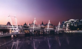
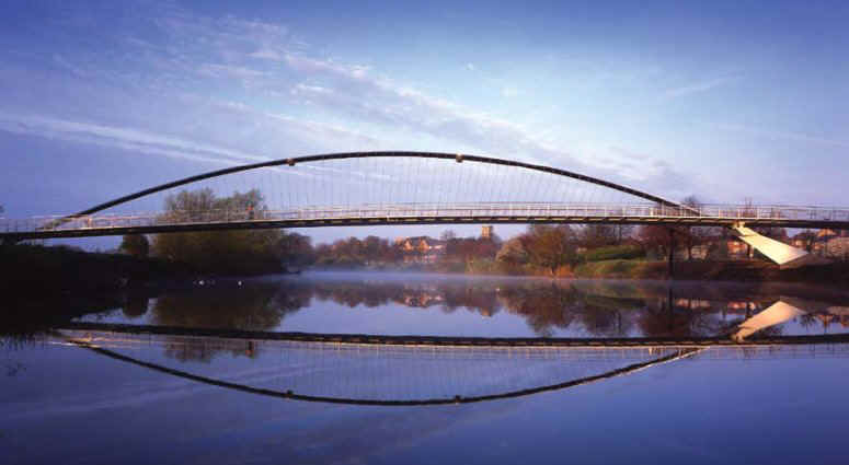
York Millennium Bridge
- cable stayed arch structure
- linear, nonlinear and dynamic analysis
- staged construction checks
Whitby Bird and Partners, (now
part of Ramboll), was a multi-disciplinary consulting engineering firm at the leading edge of
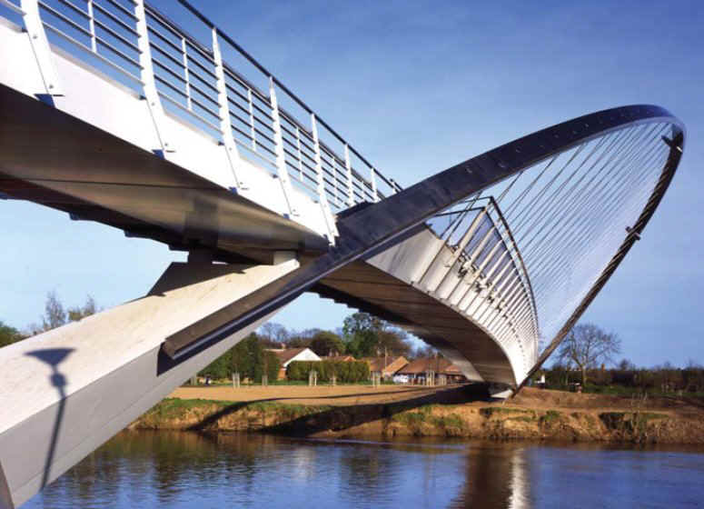
technology and innovation. Their competition-winning design for the York Millennium Bridge
across the River Ouse was inspired by the spokes of a bicycle wheel and consists of an
inclined arch with radially aligned cables supporting a slender box girder deck. To help
prove the integrity of the design LUSAS Bridge was used to perform a series of
linear, geometrically nonlinear, and dynamic analyses.
Overview
The bridge has a total length of approximately 150m with an 80m inclined
arm main span. The deck consists of a steel trapezoidal box girder with a cantilevered
front section spanning onto outriggers. The deck is suspended via 19mm diameter stainless
steel cables from the arch inclined at 50 degrees to the horizontal. The cables, at approx
1m centres, alternate between the front and rear edges of the seat which runs along the
deck, and give the appearance of a set of bicycle spokes. On the west side, the long
approach span rises from an abutment and continues over 4 intermediate piers before
reaching the main span. On the western bank the arch springs from an inclined pier. The
main span rises across the river to achieve the necessary navigational clearances before
landing at an inclined pier and concrete abutment on the eastern bank. The bridge will be
constructed on the river bank and manoevered into position using a launching barge.
 |
 |
| Beam
and shell model for linear analysis of the deck. |
Linear analysis
To extract the plate stresses for buckling and yield checks a series of
LUSAS models were developed with all the deck plates individually represented as shell
elements. The arch was modelled using beam elements, and meshed into the deck at its end.
Three models were used to represent the bridge at different stages of construction:
- Arch self weight, main span, arch with no cables
- Main span dead weight, main span, arch and cables
- Live loads and approach span dead weight. Complete bridge.
The stresses from each model were then superimposed and factored as
required to give the total stress envelope across the deck. The computational complexity
of these models for the hardware available at the time meant that only a linear analysis could be carried out.
|
Nonlinear buckling analysis
To prove the arch's stability against buckling a geometrically nonlinear
staged construction model was used. This type of model activates the supports at the
appropriate load increment to represent the construction sequence. To speed-up the
solution times for this particular type of analysis the deck and the arch were modelled as
equivalent section beam elements.
Right: Equivalent section beam model
for geometrically nonlinear buckling analysis of the arch.
|
|
Dynamic analysis
The dynamic response of the bridge to pedestrian loads was analysed in
accordance with the requirements of BS5400 Part 2 Appendix C. Eigenvalues were obtained
from the dynamic LUSAS model and a frequency response function of acceleration versus
frequency was calculated for a vertical pulsating unit force at various points on the
bridge.
The accelerations were compared to the allowable envelope of 0.6(fo) 0.5
stated in BS5400 Part 2. In addition, a dynamic analysis of the arch behaviour under wind
loading was undertaken. Joint elements were added and used to represent Tuned Mass Dampers
(TMD's) using mass, spring stiffness and Rayleigh damping coefficients. Plots of
displacement against response time were produced and TMD's were subsequently designed to
control 'damping' of the arch.
LUSAS Bridge allowed the structure to be very economically designed. The
stresses in the plates could be extracted allowing the deck section to be accurately
designed and assessed. Des Mairs, Partner in charge, said, "By using LUSAS, the
entire philosophy of the design, and that of Whitby
Bird and Partners of pushing back the boundaries of engineering, could be met. The
computer modelling enabled us to provide a very slender, elegant, and cost-effective
structure that previously could not have been designed with confidence. In addition, the
complex erection strategy could be analysed at various stages to ensure that additional
stresses were not 'locked-in' as a result of allowing the arch to fall into its final
inclined position. Preset values could be determined for this event to ensure that the
structure will behave in the manner intended."
The bridge opened to pedestrian and cycle traffic in
Autumn 2000.
"By using LUSAS, the
entire philosophy of the design, and that of Whitby
Bird and Partners of pushing back the boundaries of engineering, could be met. The
computer modelling enabled us to provide a very slender, elegant, and cost-effective
structure that previously could not have been designed with confidence." Des Mairs, Partner
in charge of project, Whitby Bird
Share this
article
Find out more
Other LUSAS Bridge case studies:
|