|
Case
Study
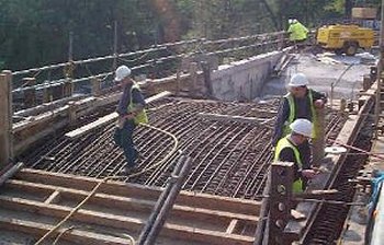
Widening and
strengthening of Kingston Bridge
- Multi-span masonry arch bridge
- 2D modelling of new arch structures
- Local transverse analysis to determine forces in spandrel walls
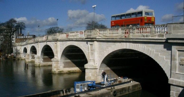
Detailed inspections of Kingston Bridge in Kingston upon
Thames, Surrey, revealed numerous defects in the 1914 structure and load assessments
resulted in vehicles of over 38 tonnes being prohibited from crossing the bridge. To
allow strengthening of the bridge for increased loadings a permanent widening scheme was
chosen to allow traffic flows to be maintained during strengthening works and to help
reduce the environmental impact during the construction work. It also provided the
opportunity to introduce permanent facilities for buses and cyclists. Designers Symonds Group Ltd used LUSAS Bridge
to model the spans of the widened structure for its client the Royal Borough of Kingston.
| The bridge widening adds 6.6 m to the previous
width of 17.5 m. New piers comprise reinforced concrete stems founded on a
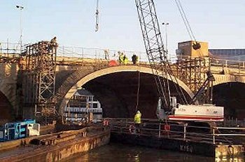
reinforced concrete pile cap with bored cast in-situ concrete piles. The piers are faced
with natural Portland Stone. Precast concrete arch units were used for
constructing the spans of the widened bridge to minimise the disruption to river traffic
during construction. The precast units forming the spans of the widened bridge are made
continuous over the crown using coupled reinforcing bars with in-situ concrete. These
precast units are faced with masonry and brick to match the existing arch profile and
finishes. An in-situ lightweight reinforced concrete saddle is cast on top of the precast
units to form a composite section. Starter bars project from the extrados of the precast
units to provide continuity with the saddle.
|
|
| |
|
| The spans of the widened bridge
were analysed using a 2-dimensional LUSAS Bridge model. Each span was
idealised as being restrained at each end by the piers. To accommodate shrinkage and
thermal effects movement joints are incorporated at the end of each arch. The
transverse stiffness of the arch was ignored in the analysis. A plane stress analysis of
unit width was therefore carried out using plane stress elements. In addition the
stiffening effects of the spandrel walls were not taken into account in the design of the
composite reinforced concrete arch barrel. A local transverse analysis was carried
out to determine the forces in the spandrel walls. End support conditions were
modelled to simulate the degree of fixity provided during the construction of the bridge
and also in the permanent situation. The analysis therefore considered the three
pinned, two pinned and fixed situations.
|
|
The superstructure was modelled globally as a five span
masonry arch using another analysis program. This analysis was used to investigate the out
of balance forces in the piers and hence to check their stability during the construction
phases and when strengthening is completed. The analysis of the lightweight
reinforced concrete saddle and brick arch composite behaviour was based on a nonlinear
analysis of the central river span. The material model for the existing brick arches
assumed no tensile stresses. The reinforced concrete saddle was modelled using linear
elastic properties based on uncracked section behaviour. The behaviour of the finite
element model was benchmarked against a single span model by comparing the order and
position of hinge formation under a point load positioned close to midspan.
For more details of the widening and strengthening project for this
bridge visit the London Bridges Engineering
Group website.
Find out more
Other LUSAS Bridge case studies:
|