 Case Study Case Study
Share this
article
Falkirk Wheel
- unique steel rotating boat lift
- linear and nonlinear analysis
- solid element modelling of movement sensitive connections
LUSAS Bridge analysis software was used as the primary analysis
tool by Tony Gee and Partners (TGP) for preliminary and
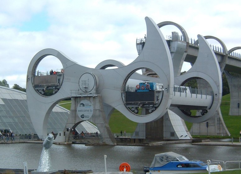
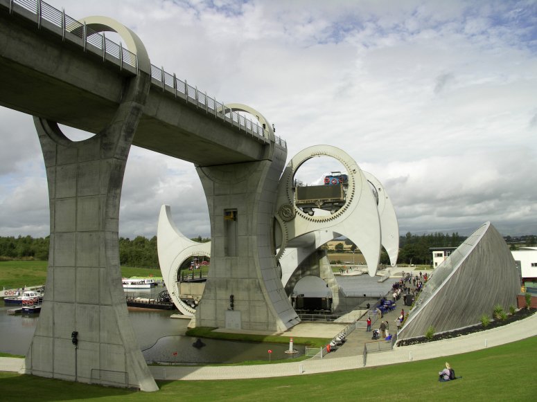
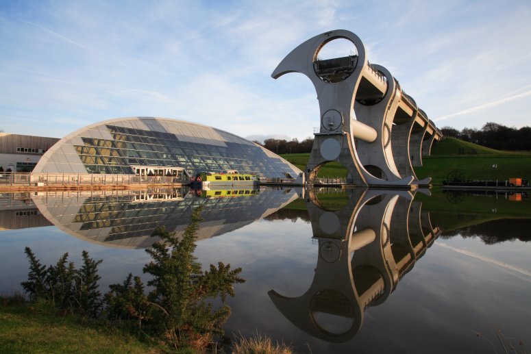
subsequent detailed design work on the Falkirk Wheel. The Wheel (as it is known) is a
unique lifting bridge designed to reconnect the Forth & Clyde and Union canals between
Glasgow and Edinburgh in Scotland. It is the world’s first rotating boat lift and the
first boat lift to be built in the UK since 1875.
Overview
The project is part of a �78m British
Waterways scheme to restore the two canals to their former glory. Construction of the
interchange section, which comprises the Wheel, an elevated aqueduct at its upper end and
a holding basin at its lower, is being led by a joint venture of Morrison and
Bachy-Soletanche. Butterley Engineering, designers and manufacturers of the wheel, Tony
Gee and Partners, structural engineering specialists and Bennett Associates, M&E
engineering specialists and architects RMJM Scotland Ltd. complete the team.
The Wheel has an outside diameter of 35m, and comprises two 1.4m wide
steel, clawed arms rotating on a 3.5 m diameter axle. A pair of 25m long, 300 m3 water
filled caissons (or "gondolas") act as containers for boats which are lifted
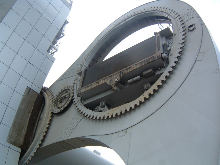
through the 24m vertical distance between the two canals. Drive is provided at one end of
the axle through a system of hydraulic planetary gear units, with stability of the
caissons ensured by a network of synchronised gears. It is capable of carrying a total
payload of 600 tonnes in winds of Beaufort Force 6 (25-31 miles per hour). Boat transfer
time is about 15 minutes.
The uniqueness of the structure required TGP to employ some innovative
and unconventional design methods. UK design codes for bridges, buildings and floating
vessels were utilised, as well as Norwegian, German and American codes for such criteria
as thin walled cylinder behaviour and constrained ice loading. A 1:50 scale model was used
in a wind-tunnel for testing aerodynamic effects. Finite element analysis using LUSAS Bridge
aided the structural design and included nonlinear solid continuum modelling of movement
sensitive connections.
| Modelling with LUSAS
Detailed analysis made use of three separate LUSAS
models:
- A 3D
linear elastic shell element model allowed for analysing the axle and arms of the main
structure.
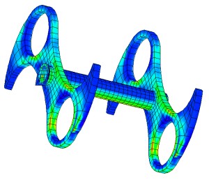
- A 3D linear elastic model using a combination of shell and beam elements
modelled one of the gondolas (shown below).
Both these models, as well as being the basis of the
material design (via the stress outputs), were particularly useful in estimating deflected
shapes and displacements, which can have a critical influence on the moving parts of the
structure.
|
|
|
A 3D nonlinear solid continuum model was used to analyse a small part of a joint
in the main axle situated just inside the clawed arm. Richard Prosser, project engineer of
Tony Gee and Partners, said: "We needed assurance that the axially loaded joint would
not prise apart, and the results from the LUSAS model formed a vital part of this
assurance."
|
|
|
|
"We needed assurance that the axially loaded joint
(
in the main axle situated just inside the clawed arm) would
not prise apart, and the results from the LUSAS model formed a vital part of this
assurance." Richard Prosser,
Project Engineer,
Tony Gee and Partners.
Share this
article
Other LUSAS Bridge case studies:
|