Case Study
Semi-automatic design of composite
bridge decks
-
Wizards to
speed-up composite bridge deck modelling
-
Composite
cross-section property calculation and section libary
-
Design
checking to Italian codes of practice
LUSAS
distributor Alhambra srl has helped many of its Italian
clients to carry-out design and checking of composite bridge decks
and bridges
using the general features available in LUSAS Bridge. Now, in conjunction
with one of its clients, Tecnostrutture srl, it has
created a set of Italian bridge wizards for use with LUSAS finite
element analysis software to
speed-up model building, analysis and checking of these type
of structures.
| Composite bridge
decks can be modelled in several different ways according to the
level of the design and the experience of the designer. Methods
include:
1. A 2D line beam
analysis where a single longitudinal beam is used to model
both steel and concrete with equivalent torsional stiffness of
the deck.
2. A 3D grillage
analysis where the steel beams and concrete slab are modelled
longitudinally and transversely with equivalent beams.
3. A composite beam /
shell analysis where beam elements are used to model the steel
beams and shell elements model the concrete slab. The line beam
is located in the surface of the slab and an offset
(eccentricity) is used in its section properties. The shown
physical distance in the image does not exist in the model and
is for visualisation purpose only.
4. Steel beam webs are
modelled with shells, each flange is modelled with beams,
bracings are modelled with beams, and the concrete slab
is modelled with shells.
5. Steel beam webs and
flanges are modelled with shells, bracings are modelled with
beams, and the concrete slab is modelled with shells.
|
 |
 |
 |
 |
 |
|
In Italy, standard bridges are
usually modelled as grillages (methods 2 and 3 above) and, as a
result, wizards were created for use with LUSAS Bridge to speed
up the modelling of composite bridge decks for these methods. |
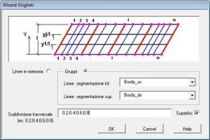
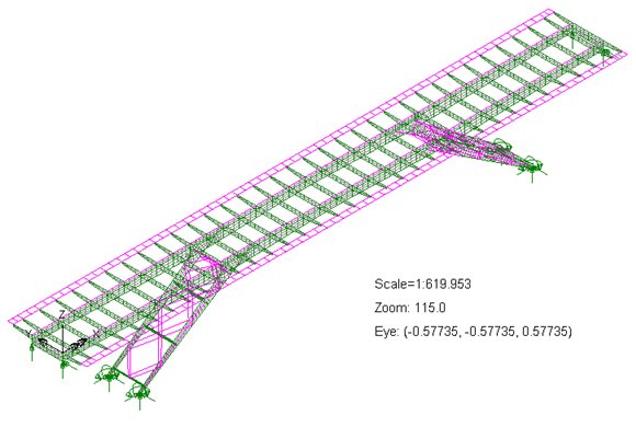
Model building
|
Models
are built by defining the two longitudinal edge beams of the bridge
then selecting the grillage wizard. Using this, a grillage or ribbed
plate model, of straight or curved form, with either single or
multiple span, can be generated. An option is provided to include
surfaces in the model to assign shell elements.
|
|
| |
|
|
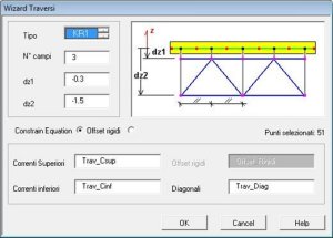
Parallel
and divergent transverse beams are allowed. Transverse beams are
automatically built and connected to the selected points by constraint
equations or by rigid beams. All similar transverse beams can be built
at the same time and several types are allowed including single
eccentric beams, and X or K transverse bracings with real
eccentricities. Bracing members are automatically grouped together for
manipulation in Modeller.
|
|
| |
|
|
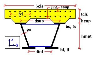
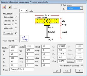
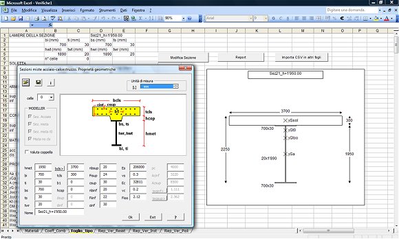
Beam
cross-section properties of composite beams are calculated for the
four analysis stages:
-
Steel beams only
-
Composite steel and concrete, at
long term
-
Composite steel and concrete, at
short term
-
Steel beam and reinforced bars
(cracked sections)
Geometric attributes are defined with
beam fleshing included. Any sections of a variable height are defined
in steps. Single beam, and mono or multi-cellular composite sections
are allowed with automatic definition of corresponding width of
concrete and of equivalent thickness of bracings.
|
|
| |
|
|
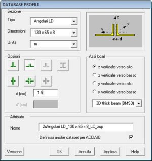
A
full set of EU profiles can be
chosen in addition to standard supplied LUSAS sections. It is also
possible to join together 2 or 4
equal / unequal angle sections and 2 channel sections.
Geometric
properties and other additional information is stored in a .csv file
and post-processed in a dedicated spreadsheet to provide elastic
stress calculation.
User attributes to allow elastic stress
calculation to be carried out in accordance with the Italian Code of
Practice are defined.
A design check is carried out in a separate
wizard.
|
|
| |
|
|
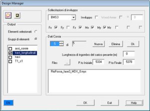
Loading / Combinations
Maximum
and minimum stresses due to
Eurocode Highway/Railway loading are obtained using a Smart
Combination approach. Results are returned at gauss points of selected
elements and are available for diagrams and contours.
In general the load type considered is
comprised of a heavy load (a number of point loads or a patch load),
and a lane load (a uniform patch load). A minimum distance between the
heavy load and the lane load can also be defined. The software will
not load spans or any parts of structure where the applied loadings
would give a relieving effect. Different dynamic factors can be
applied to loads on different spans.
|
|
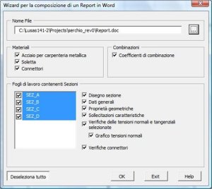
Design Checking
A wizard is also used to export
geometric section properties, node coordinates and user defined sets
of results into an Excel spreadsheet to allow design checks to be
performed. Axial stresses, shear and torsion are checked for all
construction stages. Shear in connectors and web buckling are also
examined.
|
In Excel, the same LUSAS wizard as used
to define the original grillage model is provided, so that if a stress
check fails then section data can be changed for a quick check in
Excel prior to exporting the data into LUSAS for a revised full
analysis to be re-run.
A
separate report wizard allows a list of all checks carried out to be
created in Word.
Carlo Margheriti, manager of Alhambra,
said: "In the last few years many composite bridges have been
analysed by Alhambra using LUSAS Bridge, and in doing so the number
and quality of the wizards created and used for this purpose has
increased so that they have now become a very productive modelling
tool."
He continues: "Other modelling
methods have also been used at Alhambra as and when required, for
example, by creating steel beam models where webs are modelled with
shells. Comparison of the results from the different methods has
increased confidence in our modelling of these composite
structures."
|
|
"In
the last few years many composite bridges have been analysed by
Alhambra using LUSAS Bridge, and in doing so the number and
quality of the wizards created and used for this purpose has
increased so that they have now become a very productive modelling
tool."
Carlo
Margheriti, Manager, Alhambra srl
Find out more
Other LUSAS Bridge case studies:
|
|
Software Information
|