Bridge analysis, design + assessment

Case Study

Cable stayed bridge over the River Labe at Nymburk

  • Design and construction of a longitudinally prestressed extradosed bridge
  • Detailed 3D modelling to analyse live load effects on the structure
  • Good correlation obtained with static and dynamic load tests

Cable stayed bridge over the River Labe at Nymburk

Pontex Consulting Engineers Ltd. used LUSAS Bridge to assist with its design of a slim, cable stayed bridge on behalf of the Roads and Motorways Directorate of the Czech Republic. The bridge incorporates a number of original structural elements and technologies, and provides a modern, light, and aesthetically pleasing solution to crossing the River Labe. The bridge is the first cable-stayed bridge in the Czech Republic with two planes of stays and low pylons, characteristic of an extradosed type of cable stayed bridge.

Overview

Located to the north-east of Nymburk in the Czech Republic, and situated in the flat plain of the Labe lowlands, the bridge carries the I/38 road over the River Labe as part of a by-pass scheme built to alleviate traffic congestion from the historical centre of the city. Due to the requirements of the Labe Basin Authority, a main span of  132m together with a very shallow structural depth for the bridge superstructure was required. As a result, a so-called "extradosed“ main bridge structure with low pylons was developed, representing a transition between the traditional cable-stayed bridge and a bridge with external prestressing tendons.

Elevation of Cable stayed bridge over the River Labe at Nymburk

Elevation

Cross sections of Cable stayed bridge over the River Labe at Nymburk

Typical cross-sections of approach bridge, central composite section and at pylons

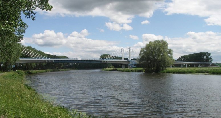
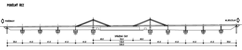
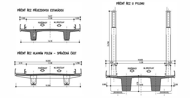
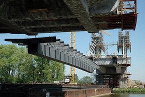
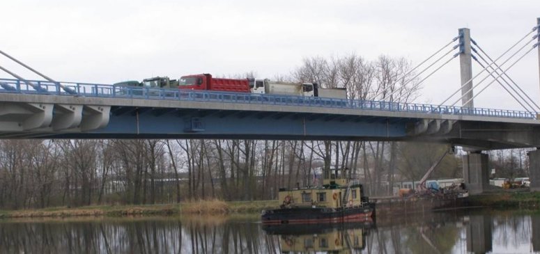
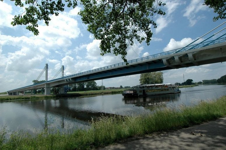
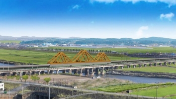
Bridge design

The complete bridge crossing has a continuous superstructure 530m long with expansion joints located only at the abutments. The main concrete bridge superstructure consists of a 132m span over the River Labe and two adjacent 41m spans that are directly connected to the approach spans.The concrete deck sections of the main span are of a symmetrical double-girder shape of variable depth and width, and are supported by sets of 3 parallel grouped stays anchored to the 16m high pylons.  The middle section of the main span was designed as a relatively lightweight composite steel-concrete drop-in structure. This 52m span comprises two main steel box girders that are tied by steel I section cross beams at 3.0m centres. The thickness of the lower and upper flanges and webs of the main steel girders vary in accordance with the magnitude of the internal forces. After being delivered to site by barges the box girders were lifted into place and welded to 700mm long steel members that were cast into the concrete structure and tied to it using longitudinal prestressing anchors fixed to the end plates. Shear studs tie a 245mm thick reinforced concrete slab to the steel girder structures.

Jacking of stays Lifting of steel girders from barge

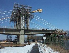
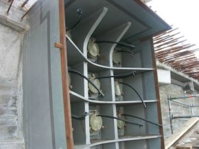
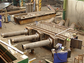
Pylons

The 16m high, heavily reinforced concrete pylons are topped with hollow steel plated box chambers for anchoring the cable stays. The anchor plates are one of the most highly stressed parts of the structure and were fabricated from 150mm thick steel plate. Welded into the front face of each anchor plate are six, 377mm diameter, 16mm thick steel tubes through which the stays were passed and then anchored. The bottom flange of the chamber is formed from 50mm thick steel plate with stiffeners to provide a uniform distribution of the forces to the concrete section. The side walls of the box are of 40mm thick plate with 50mm thick vertical stiffeners at the anchor plate locations. Steel studs, welded uniformly to the sides and top of the box chamber, bond the steel box to the self-compacting concrete that was subsequently applied.  A 600mm square manhole cover in the top of the pylon provides maintenance access.

Embedded steelwork ready to receive steel girders Steel plated pylon box assembly


Cross beams and rocking struts

At the pylon locations the bridge deck has massive cross beams which help to distribute the loading from the longitudinal girders and pylons to the bridge bearings. Prestressed anchor cross beams are also used where the cable stays are anchored to the bridge superstructure.

Piers, located where the back hangers of the bridge are anchored, are designed as rocking struts in order to be able to resist both tensile and compressive forces and to allow for expansion of the structure. The rocking struts are made of 610mm external diameter seamless steel tubes. At both ends of the strut an accurate four-shear pin joint is formed. The pin joint anchor plates are attached to the bridge deck and elements of the bridge substructure using prestressing bars.

Rocking struts beneath back cable hangar anchorages

Rocking struts beneath back cable hangar anchorage beams

Modelling in LUSAS

A detailed 3D model of the complete bridge structure including the approach viaducts was created in LUSAS. Solid hexahedral elements modelled the concrete deck and pylons. Thick shell elements modelled the steel members of drop-in span and pylon anchorage boxes. A separate 3D solid element model of a pylon box assembly was also created to investigate the localised stresses in this highly stressed part of the structure. 

Views of LUSAS model showing steel topped pylons and drop-in section

Eigenvalue analysis obtained the first 15 mode shapes and gave a good indication of the potential response of the structure.

First 4 eigenmodes

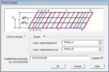
A static analysis investigated the effect of live loads in the transverse direction, and also investigated the effects of any eccentric position of live load on the longitudinal forces induced in the deck and cable stays. Because deck displacement due to off-centre vehicle loading was of interest to Pontex a number of displacement plots were produced showing displacements caused by a variety of applied loads and load combinations.

Displacement results from applied loadings

After completion of the bridge both static and dynamic load tests were carried out showing very good correlation with the LUSAS predicted results, effectively verifying the modelling approach used.

Static load testing

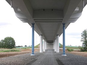
Now open

The bridge opened to traffic in May 2007. Pontex Consulting Engineers Ltd., believe that because of its location, and by the introduction and use of a number of original structural elements and technologies, the bridge will help contribute to the further development and use of modern light cable-stayed structures in the region and, in turn, become one of the most outstanding bridge structures in the Czech Republic. 

Cable stayed bridge over the River Labe at Nymburk

"By using LUSAS on this project we obtained an accurate assessment of the deck displacements caused by the static and dead loads. The easy-to-use modelling capabilities and the re-use of previously defined load patterns helped enormously with this."

Václav Kvasnička, Consulting Engineer, Pontex Consulting Engineers Ltd.


Main parties involved in this project:

  • Client: Roads and Motorways Directorate of the Czech Republic – Prague branch

  • Designer: PONTEX Consulting Engineers Ltd. 

  • Main Contractor: Joint Venture SMP CZ, a.s. + Metrostav, a.s., D.4 + PSVS, a.s.

  • Contractor for the main bridge: SMP CZ, a.s. 

  • Contractor for the approach bridges: Metrostav, a.s., D.4, together with Sub-contractor JHP mosty, s.r.o. 
  • Subcontractor for the steel work: MCE Slaný, s.r.o.

This case study was created with reference to a technical paper presented by Milan Kalny of PONTEX Consulting Engineers Ltd. at the IABSE Symposium on ‘Improving Infrastructure Bringing People Closer Worldwide’, Weimar, Germany, 17-21 September 2007.


Find out more

LUSAS Bridge

Software products

Software selection


Other LUSAS Bridge case studies:


Software Information

  Bridge / Bridge plus
green_arrow.gif (94 bytes) Software overview
green_arrow.gif (94 bytes) Modelling in general
green_arrow.gif (94 bytes) Advanced elements, materials and solvers
green_arrow.gif (94 bytes) Load types and combinations
green_arrow.gif (94 bytes) Staged construction modelling
green_arrow.gif (94 bytes) Geotechnical / Soil-structure modelling
green_arrow.gif (94 bytes) Analysis and design
green_arrow.gif (94 bytes) Design code facilities
green_arrow.gif (94 bytes) Viewing results
green_arrow.gif (94 bytes) Software customisation

  Bridge LT
green_arrow.gif (94 bytes) Software overview

  Choosing software
green_arrow.gif (94 bytes) Software products
green_arrow.gif (94 bytes) LUSAS Bridge LT
green_arrow.gif (94 bytes) LUSAS Bridge
green_arrow.gif (94 bytes) LUSAS Bridge Plus
green_arrow.gif (94 bytes) Software selection
green_arrow.gif (94 bytes) Software options

green_arrow.gif (94 bytes) Videos
 
green_arrow.gif (94 bytes) Case studies

  Application areas
green_arrow.gif (94 bytes) Footbridge design
green_arrow.gif (94 bytes) Movable structures
green_arrow.gif (94 bytes) Rail solutions
green_arrow.gif (94 bytes) Arch bridges
green_arrow.gif (94 bytes) Major crossings
green_arrow.gif (94 bytes) Soil-Structure Interaction Modelling

  Additional information
green_arrow.gif (94 bytes) Linear and nonlinear buckling analysis
green_arrow.gif (94 bytes) Curved girder analysis
green_arrow.gif (94 bytes) Integral or jointless bridges
green_arrow.gif (94 bytes) Post-tensioning
green_arrow.gif (94 bytes) Concrete modelling
green_arrow.gif (94 bytes) Interactive Modal Dynamics
green_arrow.gif (94 bytes) LUSAS Programmable Interface (LPI)

  General information
green_arrow.gif (94 bytes) Hardware specification
green_arrow.gif (94 bytes) Licencing and Networking options
green_arrow.gif (94 bytes) Software prices
green_arrow.gif (94 bytes) Documentation
green_arrow.gif (94 bytes) Links page
 

Request information


innovative | flexible | trusted

LUSAS is a trademark and trading name of Finite Element Analysis Ltd. Copyright 1982 - 2022. Last modified: March 07, 2023 . Privacy policy. 
Any modelling, design and analysis capabilities described are dependent upon the LUSAS software product, version and option in use.