Case Study
Automated
Design of Railway Culverts
-
Automated design/checking of
culverts using scripting
-
Detailed
calculation option
-
Reinforcement contour plots
Italian LUSAS distributor Alhambra
srl worked in conjunction with the engineering company Ingegneri
Associati srl to automate the modelling and design/checking of
railway culvert structures in
accordance with Italian bridge loading and reinforced concrete codes
of practice. Automating the analysis of culvert structures
using the LUSAS Programmable Interface scripting facilities produces significant time
savings over manual methods, improves the quality
of the analysis and also produces a detailed analysis report.
|
Culvert Design
Wizard
The
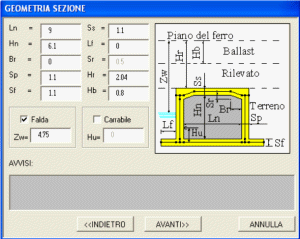
Culvert Design Wizard uses a number of user-defined dialogs to
obtain all the data required for a culvert analysis. First,
transverse culvert geometry is defined along with water levels (if
any) and whether a road is present in the culvert. This is
followed by specifying plan dimensions and the angle of any rail
lines crossing the structure. Error checking and incompatible data
entry is provided on all dialogs. An option is available to
undertake a more traditional 2D analysis considering a strip of 1m
width or to define a full 3D model of the structure using thick
shell elements.
A series of dialogs enable the following data
to be entered:
|
|
|
|
|
Cross-sectional
dimensions including:
-
Number and position of tracks
-
Angle between the railway line
and the longitudinal axis of the culvert
-
Angle between the lateral
faces and the longitudinal axis of the culvert
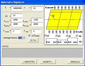
Material properties
-
Concrete properties (linear
elastic material)
-
Ground/Soil properties (modelled
as loads or linear elastic springs)
-
Availability of different
stiffness for vertical springs under the structure (using
LUSAS variations), and of horizontal springs on vertical
walls
|
|
Centrifugal, thermal and shrinkage
actions
-
Principal or secondary railway
line
-
Options for curved railway
lines, relative transverse difference in height between
rails Eb, and train design speeds
-
Thermal and shrinkage actions
A LUSAS model file is created from
the data entered with the structure having rigid zones at nodes
and with all load conditions required by the design code included. All
transverse actions are considered to act in the same direction.
|
Results processing
The LUSAS Smart Load Combination
feature is used to include all load combinations included in the
Italian design code for railway bridges and a global envelope is
produced.
Train loads are considered at three possible positions
for each railway line - each edge of
the culvert and at the centre of the span.
|
|
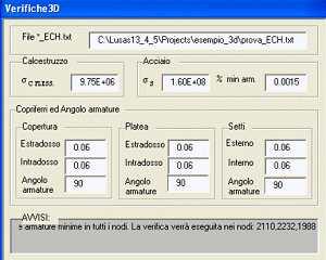
Design/checking
options
Nodes on the model where a detailed
calculation is required can be selected. Details of concrete and
steel design stresses are entered along with details of minimum
steel area, planimetric layout, and of steel cover for each
member. Using a Wood-Armer approach, the minimum amount of steel
area needed to comply with the requirements of the Italian design
code is calculated. Steel areas of transverse and longitudinal
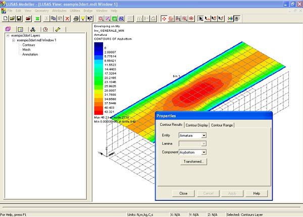
steel bars can be plotted on selected parts of the culvert.
Detailed Report
A Microsoft Word report provides a
complete description of the data input and load combinations used
in the culvert analysis and is an important contribution to the
speed-up process and the quality of the results presentation. It
provides a comprehensive listing of all model information and
results details and allows the design engineers the opportunity to add their
own comments and additional information. A contour plot of all
stresses for final maximum and minimum envelopes activated
according the most relevant stresses is also included along with a
contour plot of steel area needed in each direction and in each
part of the structure. If any user-defined nodes have been
selected on the model for detailed stress calculations then these
appear in the report also.
Benefits
Carlo Margheriti of Alhambra srl
said: �The script we developed significantly speeds up the analysis
of a typical "simple" structure, such as a railway
culvert. By modelling the structure with exact 3D geometry and
supports, and including all the loading combinations prescribed by
the code of practice the quality of the analysis is improved
significantly also.� He continues: � A simplified 2D strip
analysis option is also provided to comply with client wishes and
to help check or assess third party calculations that use the same
design assumptions.�
"The script we developed
significantly speeds up the analysis of a typical "simple"
structure, such as a railway culvert ... and the quality of the
analysis is improved significantly also."
Carlo
Margheriti, Manager, Alhambra srl
Find out more
Other LUSAS Bridge case
studies:
|