|
||||||||||||
Modelling and Analysis In consideration of the complexity associated with the analysis of skewed integral abutment bridges all analysis was carried out using LUSAS Bridge. Both 3D shell and solid modelling was employed to investigate post-continuity service conditions. Dead, superimposed dead, live and environmental loads were considered, particularly temperature and earth pressure loads. The main loadcases considered included:
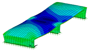
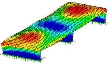
Train impact loading on the central pier to GC/RC 5510 and other load effects, including temperature, shrinkage and earth pressure on pier and abutments from superstructure. These load effects were studied using separate stand alone models of the masonry substructure. Post-continuity Live Loading A 3D shell model was developed for the proposed RC structure comprising the continuous skew deck modelled with shell elements. The integral abutments and the two piers were modelled with solid elements. It was assumed that the RC structure is seated on the masonry substructure through pinned supports at the abutment as well as the piers. These supports allowed rotation at the base about the transverse axis of the structure but no movement in any global direction. Basic load cases to UK code BD 37/01 comprising HA and HB loading were formulated using the Bridge Loading facility within LUSAS. The HB vehicle was defined as a moving load and alternative travel paths were investigated to derive the worst load effects for various members. Earth Pressure Loading While the supports were initially idealised as pins allowing rotation of the bases, it was anticipated that some of the rotational capacity could be compromised over the long term due to the build up of high earth pressures behind the abutments, degradation of the bearings and also due to possible accumulation of debris. A spring restraint was introduced to the rotation of the supports to further study this scenario. Due to the �ratcheting� effect of soil behind the abutment of IABs over several seasons, earth pressures can build up to very high values. Earth pressures were calculated in accordance with the codes, duly accounting for locked-in thermal strains at the time of closure as well as increased wall friction and applied as structural loads. The structure was analysed for lateral thrust caused by earth pressure behind the north abutment only. On the other end the structure interfaced with the retained masonry and did not have the benefit of any balancing earth pressure. Thermal Loading For this part of the analysis the model was upgraded with 3D solid elements replacing 3D shells to represent the full structural depth. A thermal gradient equation was developed in order to define a nonlinear parabolic variation of temperature through the thickness of the deck. The key reason for this upgrading was to gain a better understanding of the deformations and rotations associated with this type of loading. The ability to define a material, geometric or load variation in a structural model is a very powerful feature of LUSAS and is useful in complex analytical applications.
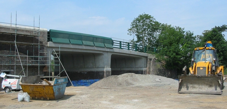
Integral Abutment Bridges There is ample evidence to suggest that the maintenance and replacement of expansion joints in bridges is an expensive and often disruptive exercise. By eliminating joints many of the maintenance issues, such as those caused by the use of de-icing salts, can be overcome. In this respect integral abutment bridges provide a desirable solution within the span and skew ranges currently specified in BD57. TGP Principal Engineer Sameer Khan said: "Whilst integral abutment bridges promise desirable long term performance, it is important to appreciate that they come with their own set of potential maintenance issues which need to be addressed during the design by careful attention to detail. It is fundamentally important to understand the behaviour of these structures under various loading conditions particularly earth pressure �ratcheting� and cyclic thermal effects which become quite complex with higher skews. In this respect it is important to develop representative analytical models of the structure so that the full implications of various load applications can be studied. Gaining a realistic estimate of the movements, rotations and deformations is as important for the design of integral abutment bridges as evaluating moments, shears and stresses".
"Detailed analysis of this integral abutment bridge provided us with a better understanding of the behaviour of the structure under the imposed loadings. LUSAS made it easier for us to assess many different variations of loading, particularly earth pressure and temperature, and also allowed us to study them in more detail than we could have done using alternative methods." Sameer Khan, Principal Engineer, Tony Gee and Partners
Find out more
|
|
Software Information
|
||||||||||
|