Bridge analysis, design + assessment

Case Study

Share this article 


Dawlish Station Footbridge

  • Design and analysis of the first Fibre Reinforced Polymer (FRP) composite bridge installed at a mainline station in the UK

  • On completion the footbridge became the first Grade II listed FRP bridge

Dawlish Station Footbridge (Image Tony Gee and Partners)

Designed by Tony Gee and subconsultant Optima Projects, with a third-party check by Parsons Brinckerhoff, Dawlish Station footbridge is an almost identical lightweight Fibre Reinforced Polymer (FRP) replacement structure for a severely corroded steel predecessor. It is the first FRP composite bridge installed at a mainline station in the UK, It is also, notably, the first Grade II listed FRP bridge. The structure aesthetically replicates the character of the original steel structure, but provides the client, Network Rail, with a much lighter and more durable solution that is expected to result in considerable through-life cost savings. Tony Gee used LUSAS Bridge analysis software to assist with its design.

Overview

Dawlish station was originally designed by Isambard Kingdom Brunel in 1830 and is grade II listed. It is situated in an extremely hostile seaside environment that caused its 17.5 metre (57'-4") long covered steel footbridge, that was reconstructed in 1937, to deteriorate progessively over the years. A detailed inspection in 2004 identified many areas of corrosion. A follow-up inspection in 2010 found the structure had deteriorated even further, and a final study in 2011 showed severe corrosion to the girder / cross girder connections. Detailed analysis found that not only could the structure not carry the specified imposed load due to corrosion of the members, but even in an ‘as new’ condition the bridge had been under-strength due to a lack of strength and stiffness in the U-frames providing lateral stability to the top flange of the plate girders

Potentially expensive like-for-like repairs were considered, as was a totally new steel replacement, but ultimately due to the extreme coastal environment, Network Rail decided to install a wholly fibre-reinforced polymer (FRP) replacement structure.


Dawlish Station steel footbridge prior to replacement. Image: Network Rail

Previous corroded steel footbridge
(Image: Network Rail)


Dawlish Station from the sea

Station location showing previous steel footbridge and its proximity to the sea

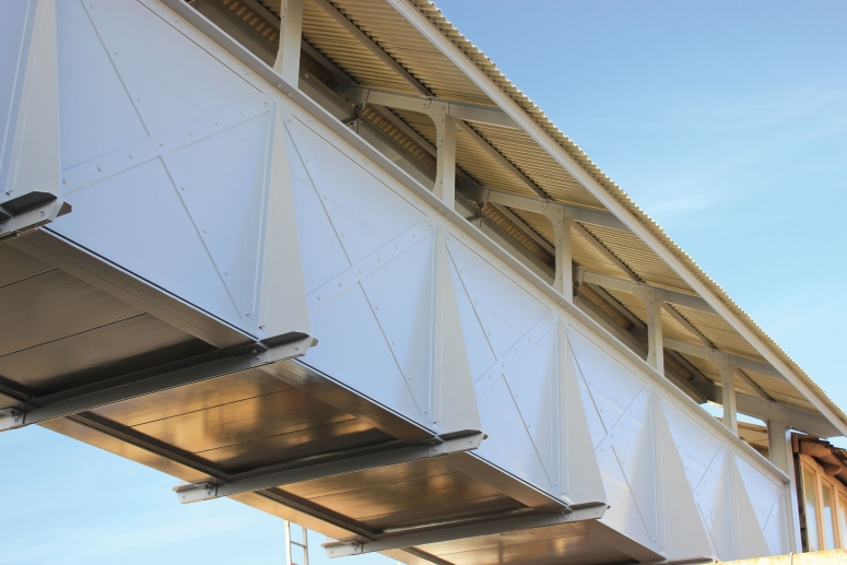
Structural form

The new bridge structure is manufactured entirely from FRP materials and mimics its predecessor in all respects. It spans the same distance, carries a 1.8 metres wide walkway, and is covered by a roof of the same style with wide overhanging eaves. The girders of the old steel bridge comprised riveted built-up sections with webs that had a clearly visible X-brace detail, which was exaggerated by corrosion patterning. This detail, together with the riveted construction, was identified as being a key part of the ‘character’ of the structure and discussions with the planning and listed building authorities identified that these features would need to be carried forward into any replacement structure. As a direct result, imitation rivet heads were bonded to the structure, and in some locations structural bolts, fitted with domed heads, provide a backup to the bonded joints.

The majority of parts are pultruded with glass fibre reinforcements and fire retardant polyester resins to achieve the required structural properties. Both the primary structure and the parapet are made up from 1.66 metre deep side girders, each formed from foam cored shear webs, moulded by film infusion using fire retardant epoxy resin and biaxial glass fibre reinforcement, capped top and bottom with pultruded angles and plates to form the girder flanges. Pultruded parts, 17.5m long, were used to fabricate these flanges and avoided the need for joints. Web stiffeners made from pultruded plate provide additional lateral support to the girders, connected to transverse angles below the deck. 

The deck is formed from lightweight ‘Composolite’ pultruded panels, that span transversely between the girders. The deck is bonded to the girders and also forms a shear panel to resist horizontal wind loading, removing the need for diagonal bracing below the deck. The deck terminates 2.7 metres from the ends of the bridge to leave room for the stairs, resulting in a long length of girder acting as a cantilever. To enable these cantilevered areas to resist large wind loading from the side, additional lateral support plates (shown green on the image below) were fitted to the flanges external to the girder.

The roof transverse frames were fabricated from back-to-back pultruded angles to form T-sections with bonded and bolted joints. The roof frames support longitudinal purlins made from pultruded box section, which support standard corrugated fibre-cement panels and also provide lateral restraint to the top of the girder. At each end of the bridge a much stiffer transverse frame is included to increase the lateral and torsional stiffness. Stair units at either end of the bridge are made from a single FRP moulding, including the stair treads, risers and side panels, hanging from the bottom flange of the bridge girder.

LUSAS half-model showing illustratative geometric properties (from a model during development). 
Inset shows a separate staircase model used for strength / frequency modelling.

Modelling with LUSAS

A number of LUSAS models were created to assist with the design of the structure, using appropriate isotropic and orthotropic materials for the various component parts. Ian Smith, Director at Tony Gee & Partners, summarises what was done: "We used a half-structure model using symmetry conditions at mid-span to carry out a strength / deflection assessment of the deck, and employed slightly simplified models for eigenvalue natural frequency and buckling analyses. For the staircases, a strength/deflection analysis of the staircase moulding (using a half-model, with symmetry along the staircase centerline), and a dynamic fundamental frequency model of the whole staircase moulding were required."

The bridge was required to withstand ‘normal’ Eurocode footbridge loading and criteria were agreed between the designers and Network Rail. Because large numbers of passengers can exit a train and then use the bridge at the same time the full ‘Load Model 4’ loading of 5 kN/m2 distributed live load was applied. Parapet loading in Eurocodes was not well resolved at the time of the design, so this was taken from older standards such as Highways Agency document TD19/06 ‘Requirements for Road Restraint Systems’. 

Wind loading was conceptually a simple code-compliant situation, although the location is exposed and the wind loads are accordingly relatively high. Simple aerodynamic stability checks indicated that the critical wind speeds for vertical or torsional vortex shedding induced vibration were above 1.25 x design mean wind speed and therefore did not require more detailed investigation. However, lightweight bridges of this type are potentially prone to dynamic response from the aerodynamic loads from passing trains, so a train buffeting assessment was performed using a number of time domain analyses. These modelled the effects of the train pressure loading advancing across the width of the deck as the train passed, where both the location and pattern of the loading varies with time.

LUSAS half-model showing beam elements (fleshed in magenta), shell elements (shaded green) and symmetry supports.

Dawlish station footbridge

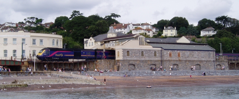
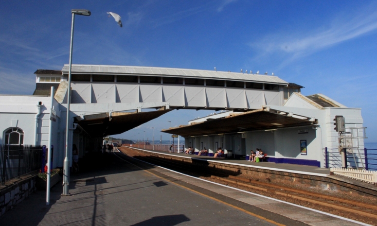
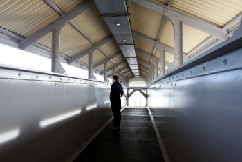
Dawlish Station footbridge after completion

Design, checking and approval.

Since the materials used in the bridge are still considered ‘novel’ by Network Rail, a rigorous design and checking process was implemented. Tony Gee and Partners was appointed to prepare the Approval in Principle document, complete the design and the Design/Checking certificate. Design work undertaken by subconsultant Optima Projects was validated by Tony Gee, and a full ‘Category 3’ independent check was carried out by Parsons Brinckerhoff. Network Rail’s own planning and listed building specialists managed the process of obtaining listed building consent, justifying a footbridge replacement rather than repair. 

The resulting footbridge authentically replicates the character of the original steel structure, whilst providing a much lighter and more durable solution than its predecessor. It is expected to result in considerable through-life cost savings for Network Rail due to reduced maintenance costs.

Dawlish station footbridge interior view (Image: First Great Western)

Interior of footbridge
 Image: First Great Western

"LUSAS is my first-choice tool for any of the structural analysis we do. For the non-standard work we undertake we need a general-purpose finite element analysis package that is not narrowly tailored to a particular market segment. LUSAS fulfils that role, letting us analyse and design with materials or for applications not yet well defined in civil engineering codes."

Ian Smith, Director, Tony Gee and Partners


Share this article 


Find out more

LUSAS Bridge

Software products

Software selection


Other LUSAS Bridge case studies:

Software Information

  Bridge / Bridge plus
green_arrow.gif (94 bytes) Software overview
green_arrow.gif (94 bytes) Modelling in general
green_arrow.gif (94 bytes) Advanced elements, materials and solvers
green_arrow.gif (94 bytes) Load types and combinations
green_arrow.gif (94 bytes) Staged construction modelling
green_arrow.gif (94 bytes) Geotechnical / Soil-structure modelling
green_arrow.gif (94 bytes) Analysis and design
green_arrow.gif (94 bytes) Design code facilities
green_arrow.gif (94 bytes) Viewing results
green_arrow.gif (94 bytes) Software customisation

  Bridge LT
green_arrow.gif (94 bytes) Software overview

  Choosing software
green_arrow.gif (94 bytes) Software products
green_arrow.gif (94 bytes) LUSAS Bridge LT
green_arrow.gif (94 bytes) LUSAS Bridge
green_arrow.gif (94 bytes) LUSAS Bridge Plus
green_arrow.gif (94 bytes) Software selection
green_arrow.gif (94 bytes) Software options

green_arrow.gif (94 bytes) Videos
 
green_arrow.gif (94 bytes) Case studies

  Application areas
green_arrow.gif (94 bytes) Footbridge design
green_arrow.gif (94 bytes) Movable structures
green_arrow.gif (94 bytes) Rail solutions
green_arrow.gif (94 bytes) Arch bridges
green_arrow.gif (94 bytes) Major crossings
green_arrow.gif (94 bytes) Soil-Structure Interaction Modelling

  Additional information
green_arrow.gif (94 bytes) Linear and nonlinear buckling analysis
green_arrow.gif (94 bytes) Curved girder analysis
green_arrow.gif (94 bytes) Integral or jointless bridges
green_arrow.gif (94 bytes) Post-tensioning
green_arrow.gif (94 bytes) Concrete modelling
green_arrow.gif (94 bytes) Interactive Modal Dynamics
green_arrow.gif (94 bytes) LUSAS Programmable Interface (LPI)

  General information
green_arrow.gif (94 bytes) Hardware specification
green_arrow.gif (94 bytes) Licencing and Networking options
green_arrow.gif (94 bytes) Software prices
green_arrow.gif (94 bytes) Documentation
green_arrow.gif (94 bytes) Links page
 

Request information


innovative | flexible | trusted

LUSAS is a trademark and trading name of Finite Element Analysis Ltd. Copyright 1982 - 2022. Last modified: March 07, 2023 . Privacy policy. 
Any modelling, design and analysis capabilities described are dependent upon the LUSAS software product, version and option in use.