Share this
article
Case
Study
West 7th Street Bridge
-
Design and
analysis of what is believed to be the world's first precast
network arch bridge
-
Analysis
of numerous post-tensioning layouts and a
variety of construction stages
-
Eigen
buckling and nonlinear analysis studies carried out to evaluate crown
deflections
The
Texas Department
of Transportation (commonly known as TxDOT) was retained by
Fort Worth city authorities to
advise on suitability of upgrading and strengthening
the existing West
7th Street Bridge to allow for wider pedestrian footways and potential future light rail
traffic. When this was proved to be not the best course of action a decision
was made to replace the structure with a new precast network arch
replacement. TxDOT chose to use LUSAS Bridge analysis software to
assist with its design of the new bridge and investigate and optimise
the post-tensioning required.
Overview
The original West 7th Street Bridge structure was built in 1913, had been extended in 1953 and was nearing the end of its service life. Investigations by
TxDOT into the suitability of upgrading and strengthening the bridge to allow for wider pedestrian footways and potential future light rail traffic, as requested by Fort Worth city authorities,
showed that extensive replacement and rehabilitation would have been
required, and this ultimately resulted in a decision being made to replace the structure.
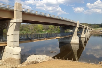
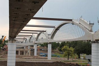
| The new bridge is constructed from precast arches, pre-tensioned floor beams and precast,
stay-in-place deck panels and is believed to be the world's first precast
network arch bridge. It comprises six 163'-6" (50m) long spans,
88'-0" (27m) wide, that carries four lanes of traffic (two in
each direction) along with two pedestrian sidewalks over the Trinity River, a park and a city street. Two planes of tightly-spaced hangers at
58" (1.47m) spacing pass cleanly through 5" (125mm) by
4" (100mm) stainless steel tubes cast into the tie at a 55 degree
angle, and allow for each of the 102 floor beams to be supported by four hangers,
eliminating the need for longitudinal stringers. 1.75" (45mm) diameter post-tensioning rods connect the floor beams to the arch. A standard
8.5" (216mm) deck spans the 9'-6" (2.9m) distance between beams. Roadway vertical curve geometry
is accommodated by adjustable floor beam pedestals. The substructure consists of
6'-6" (2m) diameter mono-shafts supporting 7'-3" x
5'-0" (2.2m by 1.55m) oval cross-section columns. |
|
Challenges faced
In designing the 23'-6" (7.2m) high concrete arches one challenge was to determine how they could be economically precast and transported. The solution was to make the arch elements as slender as possible to minimise
weight and use a span-to-rise ratio of only 0.13 to keep the centre of gravity very
low. In addition, arches were cast horizontally, before raising into a vertical position using a specially-designed lifting tower and transporting to site.
TxDOT bridge designers were aware that cracking in the arch was a real possibility during handling and if it occurred, it would lower the rib buckling limit. As a result, post-tensioning was
specified for the rib as well as the tie.
|
|
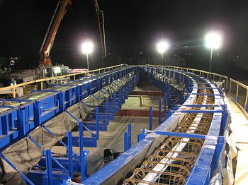
|
| Night-time
casting of arch |
Detail
of knuckle showing ducts and cooling tubes |
|
Cooling tubes were used in the knuckle regions and casting was carried out during the night to avoid excessive heat differential. The low-shrinkage, low-heat, low-permeability, high-slump, and high-strength requirement for the concrete used resulted in one of the most sophisticated mixes ever produced for a
TxDOT project.
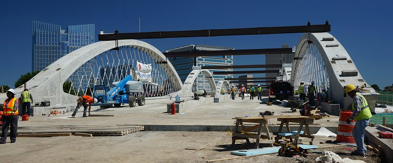
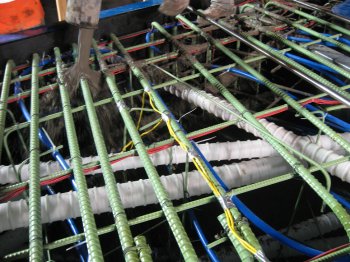
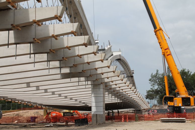
In position, the arches are
set end-to-end with only a 100mm gap, leaving no opportunity for field post-tensioning. As a result, 100% of the longitudinal tie post-tensioning had to be installed while the arches were in the casting yard. Since the arch self weight generated less than 25% of the axial service tension in the tie, the slender element experienced tremendously high compression forces prior to placing floor beams and other subsequent gravity loads. To reduce the unbraced length and prevent any lateral movement of the
2'-0" x 4'-6" (610mm x 1.4m) tie during stressing, a series of small curves was added to the ducts causing regular contact with the four 19-strand tendons. For speed, cost, and appearance, no rib cross-bracing was used. |
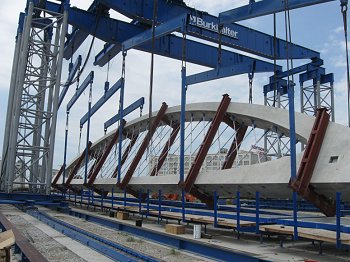 |
| Raising
of completed arch |
Modelling
with LUSAS
TxDOT used LUSAS Bridge analysis software to assist with
its detailed design of the arches. 3D
thick beam elements modelled the arch rib and tie and 3D bars
represented the hangers. To model the knuckle joints thick shell
elements were used - with this modelling methodology being verified using a 3D
solid
model
of the knuckle joint.
The
main aim of the analysis was to keep the arch concrete free of tension for durability,
aesthetics and to maintain consistency in the analytical assumption of
uncracked sections. Due to the connection details and slenderness of
the hangers, any LUSAS model that produced compression in the hangers was
deemed unsuitable and a modified configuration was evaluated. Dean
Van Landuyt,
Principal Engineer,
Texas DOT explains the process involved: "Once initial section sizing calculations
had been performed, we then used LUSAS to analyse numerous post-tensioning layouts
for a
variety of construction stages. This involved first stage post-tensioning,
raising of arches, second stage
post-tensioning, floor beam installation, deck casting, and wind and
live loading. Then, once a tendon layout that satisfied all stress limits
had been found, strength checks were made and the tendon profiles approved."
|
|
|
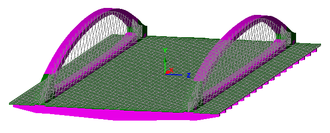
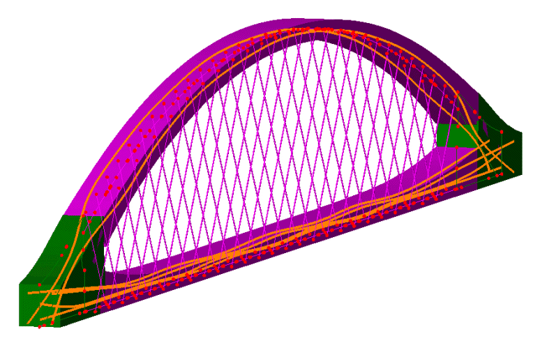
Arch modelling
methodology showing the use of thick beam elements (magenta) for
the arch rib and tie, and
shell elements (green) for the knuckle region. Tendon layout
and the use of ' outrigger' beams, used to connect the bar elements
that model the hangers to the elements in the arch rib and tie,
are also shown. |
|
|
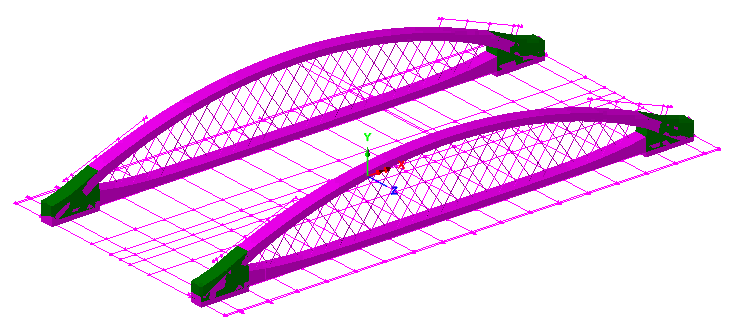
|
Construction sequence modelling for a single
span. |
Eigen
buckling studies were undertaken for initial stability analysis of the
completed structure. The
lowest Eigen buckling value of 13.3 was found to occur for the Service I
load combination comprising six lanes of traffic and wind load. The
resulting arch buckling mode showed a maximum deformation at the arch
crowns in the direction of the wind loading. A more rigorous nonlinear buckling analysis was also
performed and, for this, seven
different factored loadings from AASHTO LRFD Bridge Design
Specification Load Combinations I, III and V were examined. The LUSAS model
revealed that, even for the most severe condition, Strength III
(transverse wind), the crown deflection at a load factor of two was
only 2� (50mm) and the load-displacement curve was nearly linear.
 |
 |
| First
three eigenmodes obtained from a three lane loading assessment |
A
further LUSAS study was undertaken to investigate the negative consequences of
initial
out-of-straightness of
the arch in
the lateral direction that might arise from improper casting, improper storage,
variation in modulus of elasticity due to bleed water migration during
the horizontal casting, or some other unknown cause. To generate
the most severe initial
out-of-straightness arch
profile, an Eigen analysis was carried out using the load
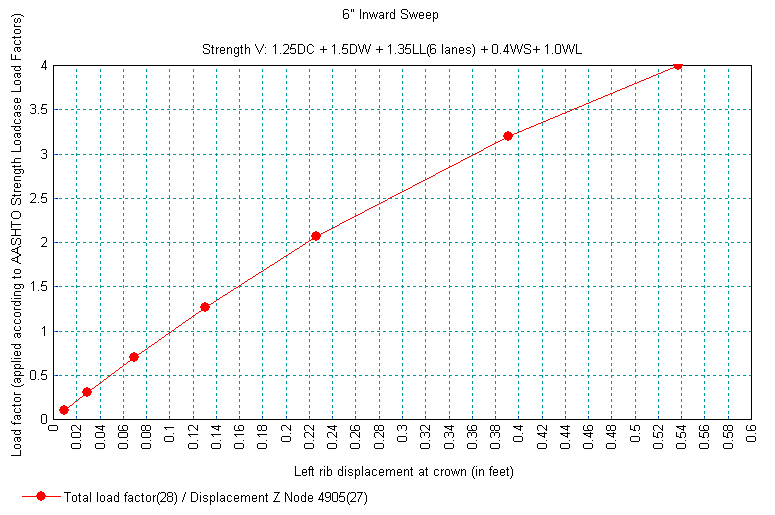
factors for the Strength V load combination with six lanes loaded. The displaced
profile was then used in a nonlinear analysis with the same
loading applied and with the initial
out-of-straightness profile
scaled so that the
crown lateral displacement was 6� (150mm). Even with this drastic initial
out-of-straightness of
the arch in
the lateral direction, the additional crown deflection was only 2 ��
(108mm) at a
load factor of two, and the load-displacement curve still had not
levelled out.
|
|
| Load
/ Displacement graph for a node at the crown of the arch |
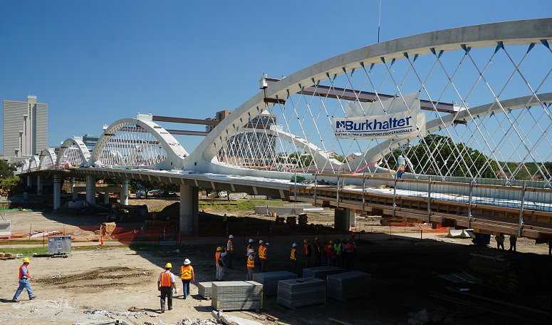
Casting of the arches
started in July 2012 and was completed in February 2013. Arch erection
began in May 2013 and was completed in 5 weeks. Floor beam
installation began in July 2013. The bridge was completed ahead of
schedule and officially opened on 15th November 2013.
|
|
|
Floor beam
setting |
|
|
|
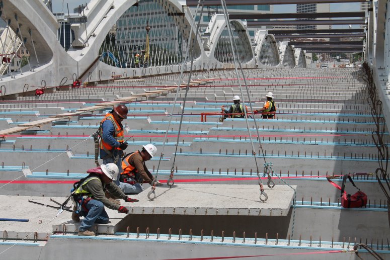
Precast deck
panel installation |
|
|
|
Bridge tour
during the 2013
PCI Annual Convention and Bridge Conference |
|
|
|
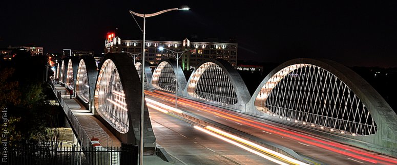
As completed.
The bridge features recessed in-arch lighting units. |
"Once
initial section sizing calculations had been performed, we then used
LUSAS to analyse numerous post-tensioning layouts for a variety of
construction stages... then, once a tendon layout that satisfied all
stress limits had been found, strength checks were made and the
tendon profile approved."
Dean
Van Landuyt,
Principal Engineer,
Texas Department of
Transportation
In the news:
Share this
article
Find out more
Other LUSAS Bridge case studies:
|
|
Software Information
|