Bridge analysis, design + assessment

Case Study 

Share this article 


Analysis and design of footbridges for the Dubai Metro light rail project

  • 3D modelling of steel truss footbridges

  • Eigenvalue analyses to derive mode shapes and mass participation factors

  • Assisted the design of large number of footbridges in a timely and efficient manner

Artists impression of footbridge and entrance structure

The Red and Green Lines of the Dubai Metro light rail scheme are being constructed as a Design-Build contract by a consortium of international contractors. Atkins, one of the world’s leading engineering and design consultancies, is the lead designer to the major civil contractor of the Dubai Rapid Link (DURL) Consortium and is carrying out the full multi-disciplinary design and project management of the civil works for the project. Atkins used LUSAS Bridge analysis software to assist with its analysis and design of a large number of steel truss footbridges used to provide pedestrian access to the elevated stations on the project and to permit the crossing of roads along the route.


Overview

The 52km long Red and 24km long Green Lines of the Dubai Metro are accessed via 47 stations, some of which are at-grade, most are elevated, and ten are underground. A total of 205 steel truss footbridges provide 24-hour, air-conditioned access for the general public to enter the elevated stations and also permit the crossing of a variety of roads along the route. 

Prior to installation each footbridge is fully assembled (incorporating glazing, external cladding, internal fixtures and finishes, and electrical and mechanical items) resulting in the largest footbridge weighing well in excess of 200 tonnes. Special self-propelled modular transporters are then used to transport the footbridges into position from their off-site assembled location and to subsequently lift them onto piers that have flared pierheads similar in style to those seen on the main viaduct structures of the Metro.

Modelling and analysis

A modular design approach was used to assist with the structural design of the footbridges. Using LUSAS Bridge, the longest of each of the main footbridge types were analysed. These comprised a non-travelator type, a travelator type, and a low height option. Additionally five ‘special cases’ had also to be assessed.

Transportation of footbridges


Travelator and non-travelator footbridge cross-sections

Travelator and non-travelator footbridge cross-sections

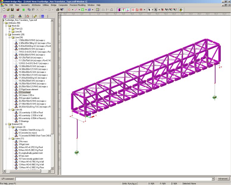
For each footbridge, 3D thick beam elements modelled the primary structural members of the streel truss, crossheads, and concrete pierhead and pier. Piled supports were modelled using the equivalent cantilever method. Joint elements of appropriate stiffness and freedoms represented the articulation of the bearings. Lumped masses, applied throughout the model using joint elements, and with an appropriate eccentricity, modelled the mass distribution of the cladding and finishes to the roof, walls and floor.

Partially fleshed 3D LUSAS model of a long-span non-travelator footbridge

Partially fleshed 3D LUSAS model of a long-span non-travelator footbridge

From a close inspection of the mass-participation factors, eigenvalues and frequencies obtained from each LUSAS analysis the primary longitudinal, vertical, lateral and torsional modes could be identified. Graphs of total mass participation plotted against frequency showed quite clearly when particular amounts of structural mass became excited for certain freqencies. In addition, animations of selected eigenmodes permitted easy visualisation of the true structural response.

First longitudinal mode

First lateral mode

First longitudinal mode

First lateral mode

Animation of first vertical mode

First vertical mode

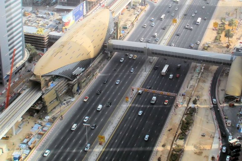
Design and checking

Steel design was to BS 5400-3:2000 and BS EN 1993-1-8:2005. Post-LUSAS analysis calculations carried out on the main footbridge types included vibration serviceability checking to BD 37/01to ensure that the structure was not overly excited by pedestrian use, and aerodynamic checking to BD 49/01.

Manuela Chiarello, engineer on the project said: "When we did the analysis of the longest non-travelator footbridge type with LUSAS and checked for susceptibility to aerodynamic excitation as defined by BD 49/01 we found that, whilst the structure passed the vortex excitation check, it didn’t comply with the divergent amplitude response check (for galloping) essentially because it was an enclosed structure that was just taking too much wind load, so a wind tunnel test was additionally carried out. This proved the structure wasn’t actually susceptible to galloping."

David A Smith, Regional Head of Bridge Engineering at Atkins said: "The use of a modular design approach in conjunction with detailed LUSAS analyses of the main footbridge types enabled us to design the large number of footbridges required for the project in a very timely and efficient manner."

The Red Line was officially opened in September 2009. The Green Line opened in 2010.

Other analyses undertaken by Atkins on the Dubai Metro light rail project using LUSAS include:

Aerial view of Dubai Metro Financial Centre station and footbridge

Aerial view of Dubai Metro Financial Centre station and footbridge access

"The use of a modular design approach in conjunction with detailed LUSAS analyses of the main footbridge types enabled us to design the large number of footbridges required for the project in a very timely and efficient manner."

David A Smith, Regional Head of Bridge Engineering, Atkins


Share this article 


Find out more

LUSAS Bridge

Software products

Software selection


Other LUSAS Bridge case studies:

Software Information

  Bridge / Bridge plus
green_arrow.gif (94 bytes) Software overview
green_arrow.gif (94 bytes) Modelling in general
green_arrow.gif (94 bytes) Advanced elements, materials and solvers
green_arrow.gif (94 bytes) Load types and combinations
green_arrow.gif (94 bytes) Staged construction modelling
green_arrow.gif (94 bytes) Geotechnical / Soil-structure modelling
green_arrow.gif (94 bytes) Analysis and design
green_arrow.gif (94 bytes) Design code facilities
green_arrow.gif (94 bytes) Viewing results
green_arrow.gif (94 bytes) Software customisation

  Bridge LT
green_arrow.gif (94 bytes) Software overview

  Choosing software
green_arrow.gif (94 bytes) Software products
green_arrow.gif (94 bytes) LUSAS Bridge LT
green_arrow.gif (94 bytes) LUSAS Bridge
green_arrow.gif (94 bytes) LUSAS Bridge Plus
green_arrow.gif (94 bytes) Software selection
green_arrow.gif (94 bytes) Software options

green_arrow.gif (94 bytes) Videos
 
green_arrow.gif (94 bytes) Case studies

  Application areas
green_arrow.gif (94 bytes) Footbridge design
green_arrow.gif (94 bytes) Movable structures
green_arrow.gif (94 bytes) Rail solutions
green_arrow.gif (94 bytes) Arch bridges
green_arrow.gif (94 bytes) Major crossings
green_arrow.gif (94 bytes) Soil-Structure Interaction Modelling

  Additional information
green_arrow.gif (94 bytes) Linear and nonlinear buckling analysis
green_arrow.gif (94 bytes) Curved girder analysis
green_arrow.gif (94 bytes) Integral or jointless bridges
green_arrow.gif (94 bytes) Post-tensioning
green_arrow.gif (94 bytes) Concrete modelling
green_arrow.gif (94 bytes) Interactive Modal Dynamics
green_arrow.gif (94 bytes) LUSAS Programmable Interface (LPI)

  General information
green_arrow.gif (94 bytes) Hardware specification
green_arrow.gif (94 bytes) Licencing and Networking options
green_arrow.gif (94 bytes) Software prices
green_arrow.gif (94 bytes) Documentation
green_arrow.gif (94 bytes) Links page
 

Request information


innovative | flexible | trusted

LUSAS is a trademark and trading name of Finite Element Analysis Ltd. Copyright 1982 - 2022. Last modified: March 07, 2023 . Privacy policy. 
Any modelling, design and analysis capabilities described are dependent upon the LUSAS software product, version and option in use.