Bridge analysis, design + assessment

Case Study

Redesign of Estero Parkway Flyover 

  • Steel box girder redesign in place of cast-in place concrete box

  • Linear static modelling using beam and shell elements

  • Significant cost savings made

Estero Parkway under construction (Photo: ZEP Construction)

Photo: ZEP Construction

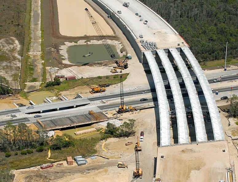
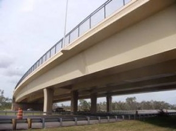
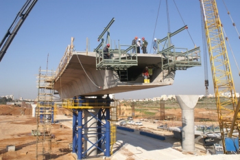
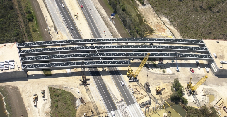
Finley Engineering Group, Inc. (FINLEY) used LUSAS Bridge for its engineering redesign of the Estero Parkway Flyover in Fort Myers, Florida, for the contractor, ZEP Construction. In doing so, FINLEY’s four-steel box girder design produced significant savings in construction costs over an initially proposed cast-in-place concrete box girder design. As the result of the engineering redesign done using LUSAS and cost-effectiveness measures taken by Zep Construction, $2.94 million will be passed to the project’s owner, Lee County, Florida, as a value engineering credit. 

Overview

The Estero Parkway Flyover is 561 feet long, with spans of 340 and 221 feet, and approximately 116 feet wide. It extends Estero Parkway over Interstate 75, connecting with Ben Hill Griffin Parkway, which then meets with Corkscrew Road to the southeast of the city. 

FINLEY’s redesign replaces previously proposed twin, cast-in-place concrete box girders with a single, four-steel box girder design. This redesigned solution provides significant savings with the elimination of a large falsework support system, reduced construction time, reduced foundation design requirements and simplified construction. By using shallower steel girders, shallower approach grades can be used, saving fill and construction time. It also means that the contractor can erect the bridge in longer sections meaning fewer obstructions in the roadway.

The new design uses a staged temporary tower support scheme to optimize the efficiency of the steel section which allowed the steel bridge solution to be more attractive against a cast-in-place concrete one. The redesign also enhances overall project safety with the elimination of the falsework system over the interstate and reduces the risks associated with a constrained traffic pattern through the falsework system.

Bridge Construction

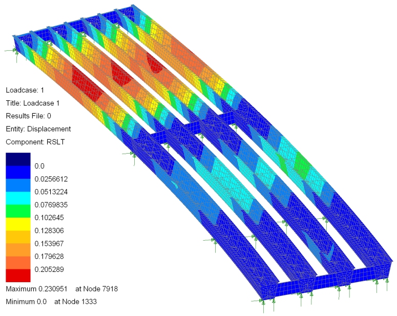
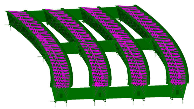
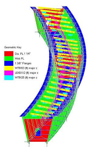
Each curved steel box girder comprises webs of 1" thick plate and top and bottom flange thicknesses of 1-1/4" plate. Internal X bracing formed of WT and L sections is used in conjunction with diagonal top flange bracing of WT sections to stiffen the girders. At supports, 1-1/4" thick internal diaphragms with access holes are used with end diaphragms of 1/2" thick web and flange plates connect adjacent girders.

Modelling and analysis

In all, 15,000 quadrilateral thick shell elements modeled the 4 box girders and stiffeners in the bridge structure. Customized displays of assigned geometric attributes such as steel plate sizes were produced by visualizing each thickness in turn - especially useful for checking that the correct thickness assignments were made. This in conjunction with the LUSAS groups facility, which permits easy definition and isolation of each sub-element of the model for display and model building purposes, and the fleshing facility, which helps ensure the correct orientation of standard section sizes is obtained, helped FINLEY to build the model 
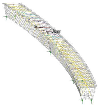
in a very straightforward manner. Pinned supports including the temporary supports beneath the longest span were assigned to the model 
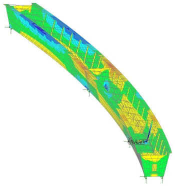
and a linear static analysis was carried out. From the LUSAS analysis overall girder displacements and stresses in the bracing struts and girder plates were obtained for the applied loading.

Resultant displacements from deck pour loading

Resultant displacements from deck pour loading

Typical absolute stresses in girder 1 from deck pour

Typical absolute stresses in girder 1 from deck pour

Colour coded axial stresses in girder 1 bracing struts from deck pour

Estero Parkway under construction (Photo: ZEP Construction)

Photo: ZEP Construction

Benefits obtained

The project was completed in September 2009. Craig Finley, president of FINLEY said: "We see this as a great example of what can happen with value engineering when the owner, contractor and engineer come together to create a design that takes the contractor’s strengths into account and that utilizes the best material and the most appropriate software for the challenges of the project." He added: "In this case, the redesign from concrete to steel had an overall positive effect on the cost, schedule, and efficiency of the bridge, and the use of LUSAS helped us meet our design deadline and to prove an alternative bridge design that will ultimately save the client a great deal of money in construction costs.". This view was echoed by Donald Deberry, P.E., public works operations manager for Lee County. "We are obviously pleased," he said. "We always appreciate working with engineers and contractors who are willing to take a second look at projects and find ways to give the public more bang for their buck."

"The use of LUSAS helped us meet our design deadline and to prove an alternative bridge design that will ultimately save the client a great deal of money in construction costs."

Craig Finley, President, Finley Engineering Group, Inc.


Find out more

LUSAS Bridge

Software products

Software selection


Other LUSAS Bridge case studies:


Software Information

  Bridge / Bridge plus
green_arrow.gif (94 bytes) Software overview
green_arrow.gif (94 bytes) Modelling in general
green_arrow.gif (94 bytes) Advanced elements, materials and solvers
green_arrow.gif (94 bytes) Load types and combinations
green_arrow.gif (94 bytes) Staged construction modelling
green_arrow.gif (94 bytes) Geotechnical / Soil-structure modelling
green_arrow.gif (94 bytes) Analysis and design
green_arrow.gif (94 bytes) Design code facilities
green_arrow.gif (94 bytes) Viewing results
green_arrow.gif (94 bytes) Software customisation

  Bridge LT
green_arrow.gif (94 bytes) Software overview

  Choosing software
green_arrow.gif (94 bytes) Software products
green_arrow.gif (94 bytes) LUSAS Bridge LT
green_arrow.gif (94 bytes) LUSAS Bridge
green_arrow.gif (94 bytes) LUSAS Bridge Plus
green_arrow.gif (94 bytes) Software selection
green_arrow.gif (94 bytes) Software options

green_arrow.gif (94 bytes) Videos
 
green_arrow.gif (94 bytes) Case studies

  Application areas
green_arrow.gif (94 bytes) Footbridge design
green_arrow.gif (94 bytes) Movable structures
green_arrow.gif (94 bytes) Rail solutions
green_arrow.gif (94 bytes) Arch bridges
green_arrow.gif (94 bytes) Major crossings
green_arrow.gif (94 bytes) Soil-Structure Interaction Modelling

  Additional information
green_arrow.gif (94 bytes) Linear and nonlinear buckling analysis
green_arrow.gif (94 bytes) Curved girder analysis
green_arrow.gif (94 bytes) Integral or jointless bridges
green_arrow.gif (94 bytes) Post-tensioning
green_arrow.gif (94 bytes) Concrete modelling
green_arrow.gif (94 bytes) Interactive Modal Dynamics
green_arrow.gif (94 bytes) LUSAS Programmable Interface (LPI)

  General information
green_arrow.gif (94 bytes) Hardware specification
green_arrow.gif (94 bytes) Licencing and Networking options
green_arrow.gif (94 bytes) Software prices
green_arrow.gif (94 bytes) Documentation
green_arrow.gif (94 bytes) Links page
 

Request information


innovative | flexible | trusted

LUSAS is a trademark and trading name of Finite Element Analysis Ltd. Copyright 1982 - 2022. Last modified: March 07, 2023 . Privacy policy. 
Any modelling, design and analysis capabilities described are dependent upon the LUSAS software product, version and option in use.