Case Study
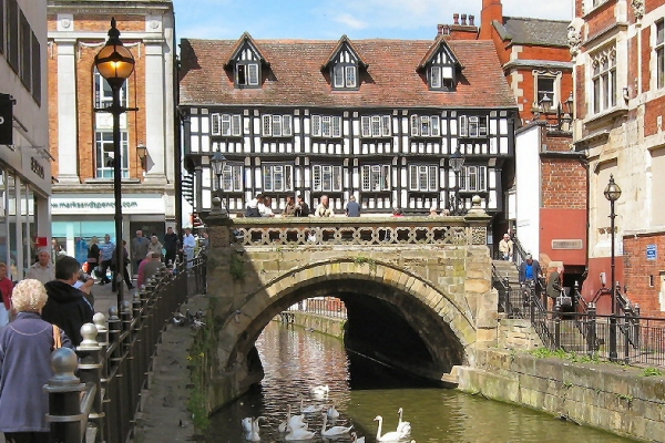
High Bridge medieval masonry arch
- masonry arch structure
- linear and nonlinear analysis
- load capacity of structure proved
Sheffield City
Council’s Design and Property (Structures Division) used LUSAS Bridge to
undertake an assessment (strength) check of High Bridge, a 13th century quadripartite arch
bridge on behalf of Lincolnshire County Council, the bridge’s owner. High Bridge,
which carries Lincoln’s main pedestrian thoroughfare, had been structurally assessed
twice before with conflicting outcomes. The LUSAS analysis provided an independent third
assessment and proved the structure was safe for the imposed loading.
History
The High
Bridge on Lincoln High Street dates from 16th century and carries
the road, once one of the two main routes through the centre of
Lincoln, over the River Witham. The area is now pedestrianised. The
bridge is the only one in Britain still in use today with a secular
a medieval building still standing on it and incorporated in its
structure are the stone ribs of what is believed to be the second
oldest masonry arch bridge in the country. Built of stone with later
brickwork, the bridge has been extended in various stages -
including an extension to accommodate a chapel in 1235 and a range
of timber buildings in 1540-50.
|
Background to the
analysis
The first of the earlier analyses ‘failed’ the structure and
concluded that the bridge was inadequate for pedestrian loading due to permissible tension
in the masonry being exceeded. Next, Lincolnshire County Council carried out an in-house
assessment using a serviceability limit state check under nominal loads with a ‘line
of thrust’ method. Unlike the first analysis, this took the formation of a hinge as
the failure criterion, implying an acceptance of tension up to the formation of the first
hinge. This assessment deemed the structure to have ‘passed’.
Lincolnshire’s approach was felt to be a more rational basis for determining
‘failure’ than the onset of tension since many masonry arches regularly
experience tension and remain perfectly viable structures. Because of this, Sheffield
City Council used
the plane stress ‘concrete model’ in LUSAS to mimic the behaviour of the
masonry. An ultimate limit state, rather than serviceability state, analysis was applied,
because the issue was considered to be primarily one of structural safety.
|
|
|
|
|
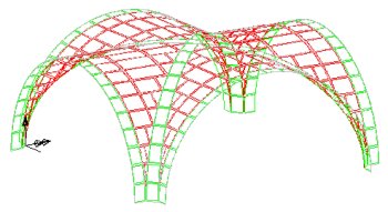
Modelling in LUSAS
The technique used was to trace
crack formation as nominal loads, i.e. without partial load factors, were applied
incrementally with manual amendment of the model between each analysis. Repeated
re-appraisal of the structure’s stiffness between runs was necessary since the model
allows cracks to develop and propagate as the load increases and the structure degrades.
As the model developed, the load factor achieved increased. This procedure continued with
the aim of reaching an acceptable value. To reduce processing time, a series of linear
analyses were done prior to a full nonlinear analysis.
The initial linear analyses determined that ‘out of balance’
effects from applying pedestrian loading to quarters of the plan area were minimal. The
worst load case was shown to be pedestrian loading of 5kN/m2 over the entire plan of the
structure. This allowed a simpler 3D quarter model to be employed thereafter, giving
faster results.
|
|
|
|
|
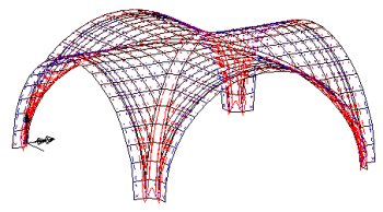
Additional linear analyses
found that support conditions were critical to the mode of failure. With the supports
rigid in respect of vertical settlement, as initially modelled, failure in the
structure’s ‘legs’ occurred very early in the loading regime. Truly rigid
supports were felt to be unrealistic, so springs were introduced, resolving the premature
leg failure. A final refinement was to introduce spring lateral restraints. These replaced
the earlier rigid ones (which modelled lateral soil pressures) since it was felt that
complete rigidity was unrealistic and furthermore had caused problems for the legs.
The cumulative effect of all the modelling changes was to raise the
structure’s load factor to 3.43, an acceptable figure, and proving the safety of High
Bridge for pedestrian loading. Achieving this outcome depended upon certain assumptions,
as well as lateral support derived from the surrounding soil and adjacent buildings. This
point was made clear to the Client in case future construction or demolition work nearby
affected this beneficial soil pressure.
|
|
In this analysis the following assumptions are pertinent:
- A condition factor of unity was assumed.
- Lateral soils pressure was earth pressure ‘at rest’.
- The only live load was pedestrian at 5 kN/m2.
- A linear stress/strain model was assumed, but a parabolic profile is more
likely for masonry.
- The compressive strength of masonry was taken as 15 N/mm2.
- The formation of tension and hinges were accepted.
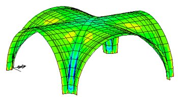
Failure was deemed to occur when the analysis failed to converge at the
‘n’th iteration. The load at the ‘n-1’th iteration, divided by the
nominal load, provided a ‘load factor’ value. It is implicit in this approach
that cracking is permitted, as is the formation of one or more hinges, but not a
mechanism.
Find out more
Other LUSAS Bridge case studies:
|
|
Software Information
|